English
INSTRUCTIONS FOR INSTALLATION
the wall.Press the inlet pipe back in such a way that the
end of the pipe is level with the turned-back edge of the
mounting sheet.
From the outside,bring the wall grid with its attached
tension members into the inlet pipe.Bend the tension
members a little outwards,so that they will jam slightly in
the inlet pipe,keeping the grid in its place.Keep the mark
"Top" up when placing the wall grid.Slide the two fasten-
ing clamps (5) over the tension members (6),taking care
that the fastening clamps catch on the turned-back edge
of the mounting sheet.Fix the screw-nuts onto the ten-
sion members and tighten them by hand.Place the fasten-
ing clamps onto the horizontal centre line of the inlet
pipe.See also the marks in the mounting sheet.
The exterior wall duct with telescopic inlet
pipe
This is suitable for wall thicknesses of 250 – 440 mm
without shortening the parts of the inlet pipe.By short-
ening the pipe’s parts,this exterior wall duct can be
adapted for thicknesses of 70 – 250 mm.The outlet pipe
should be adjusted.The tension members attached to the
wall grid can be shortened after the wall duct has been
mounted.If the telescopic inlet pipe is applied for wall
thicknesses of 70 – 250 mm,both parts of the pipe
should be shortened,i.e.:
• the part of the inlet pipe on the side of the wall grid
equal to the thickness of the wall
• the part of the pipe on the side of the heater to a length
equalling the wall thickness minus 20 mm.
CAUTION: do not cut the pipe parts on the side
where the fastening clamps have been applied.
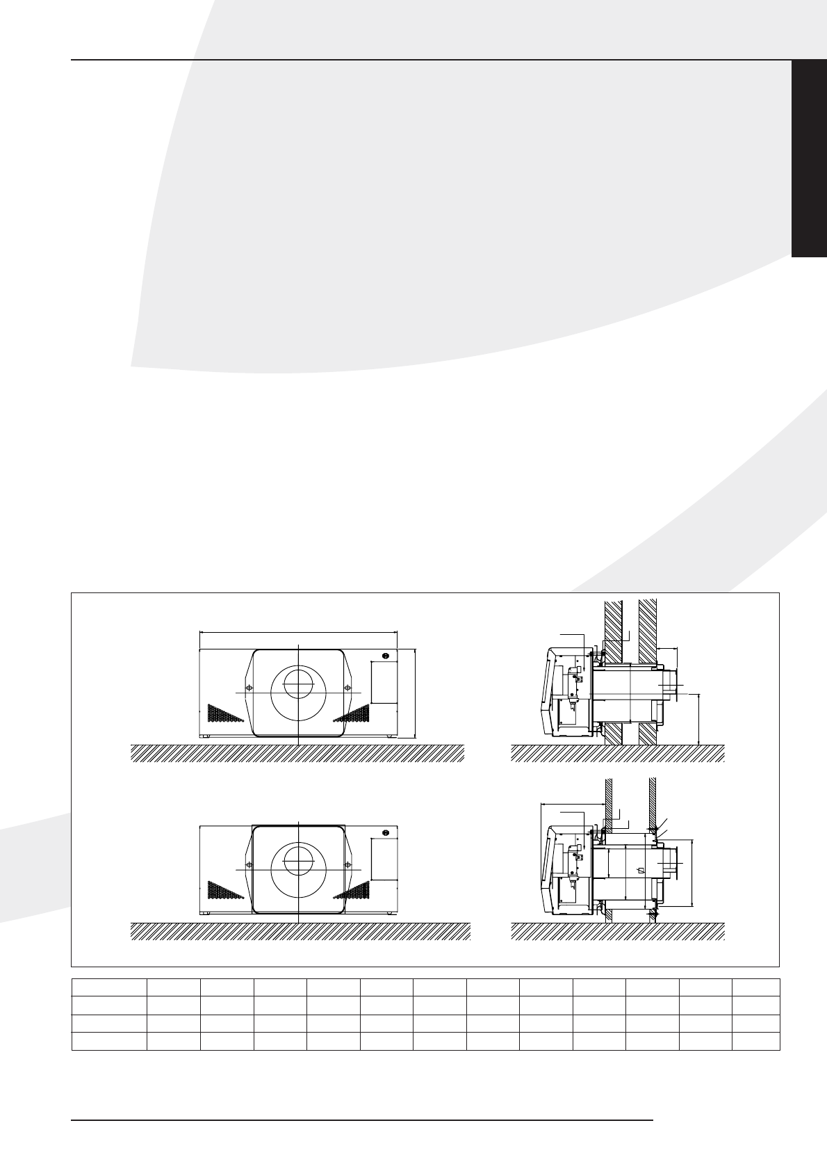
Installation of the wall duct with telescopic
inlet pipe (fig. 3)
From the outside,put the wall grid,together with the
attached half inlet pipe into the created wall opening,
keeping "Top" up when placing the wall grid.Slide the
other half of the inlet pipe through the mounting sheet
(2),making sure that the inserted fastening clamps (5) lie
on the horizontal centre line (see the marks in the
mounting sheet).They should catch on the turned-back
edge of the mounting sheet.
Attach the sealing ring (3) and the wall ring (4) to the half
inlet pipe (see ffigure for the correct order).Take the
whole and,from the inside,slide the half inlet pipe
through the created wall opening into the part of the
inlet pipe already mounted.While doing so,make sure the
the two tension members (6) stick through the fastening
clamps.Press the mounting sheet up to the wall.Appply
the screw-nuts onto the tension members (6) and tighten
them by hand against the fastening clamps (5).
NL 31 / NL 51