17
ENGLISH
Installing the hot air circulation
system
jacket of the fireplace absolutely must
be conducted into the indoor environ-
ment. This ensures compensation for the
air that is expelled from the fireplace
through the flue, while it is operating,
and at the same time achiehe heating
function.
The hot air is fed into the rooms through
outlet pipes connected to the holes in the
upper wall of the shell with aluminium
tubes Ø 14 cm.
If hot air is being channelled to rooms
other than the one where the fireplace is
installed it is essential to ensure the
return of the air itself to the room with
the fireplace through grilles located at
the base of the walls or through spaces
under doors.
The pipes must not be any less than 14
cm in diameter so that the air does not
exceed a speed of 5 m/sec thus avoiding
bothersome noises and an excessive
drop in pressure due to friction. It is
important that the route of the pipes is as
straight as possible.
The aluminium tubes can be hidden with
chests of drawers, faux or recessed
beams, in any case it is essential that
they are very well insulated.
The channelling ducts can be a maxi-
mum length of 6 ÷ 8m each for version
V, and 4 ÷ 5 m each for version N.
This length is reduced by 1.2 m for each
curve and for each pipe outlet as a result
of the loss in pressure.
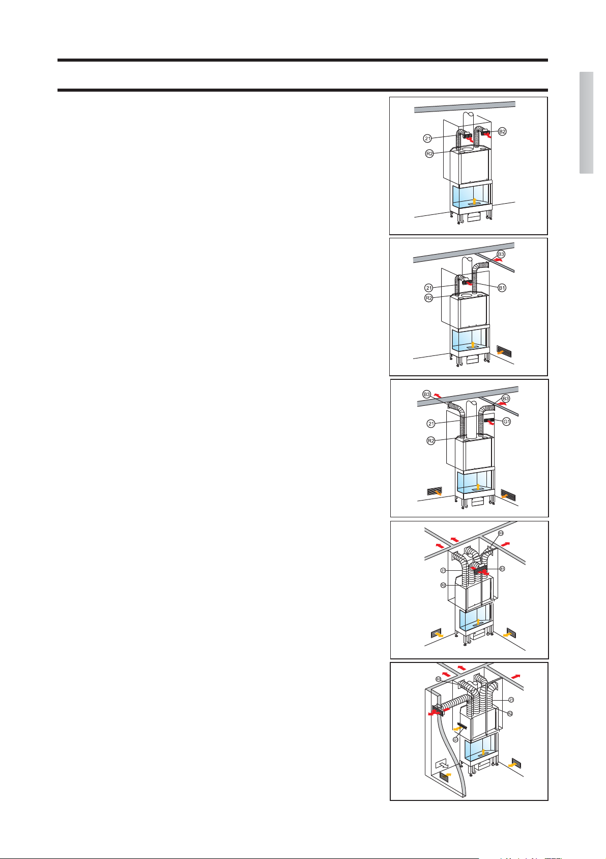
Installing the hot air circulation Kit
We offer the following hot air channel-
ling kits.
Kit One/bis
only for the room where the fireplace
is installed
- attach the two fittings "R2" to the
holes on the shell
- insert the two pipes (21) and secure
them with their clamps
- build the frames with the fittings with
the two outlets "B2" into the wall on
the top part of the fireplace mantle
- connect the two aluminium pipes to
the fittings and secure them with
clamps, and snap on the front grilles
Kit Two/bis
for the room where the fireplace is
installed, plus an adjacent room
- attach the two fittings "R2" to the
holes on the shell
- insert the two pipes (21) and secure
them with their clamps
- build the frame with the fitting for
outlet "B1" into the wall on the top
part of the fireplace mantel
- build the frame with the fitting for
outlet "B3" into the wall of the room
requiring heating
- connect the two aluminium pipes to
the fittings and secure them with
clamps, and snap on the front grilles
Kit Three/bis
for the room where the fireplace is
installed, plus two
adjacent rooms
- attach the two fittings "R2" to the
holes on the shell
- insert the two pipes (21) and secure
them with their clamps
- build the frames with the fitting for
the two "B3" outlets into the walls of
the rooms requiring heating
- mount slit "G1" in the top part of the
mantel to allow for ventilation inside
the mantel itself
- connect the two aluminium pipes to
the fittings and secure them with
clamps, and snap on the front grilles
Kit four/bis
for the room where the fireplace is
installed, plus three adjacent rooms
- attach the four fittings "R2" to the
holes on the shell
- insert the four pipes (21) and secure
them with their clamps
- recess the frame with the fitting for
outlet "B1" into the wall on the top
part of the mantel
- recess the frames with the fitting for
the three "B3" outlets into the walls of
the rooms requiring heating
- connect the four aluminium pipes to
the fittings and secure them with
clamps, and snap on the front grilles
Kit five/bis
for the room where the fireplace is
installed, plus four adjacent rooms
- attach the four fittings "R2" to the
holes on the shell
- insert the four pipes (21) and secure
them with their clamps
- recess the frames with the fitting for
the four "B3" outlets into the walls of
the rooms requiring heating
- mount a "G1" slit onto the top part of
the mantel to allow for ventilation
inside the mantel itself
- connect the four aluminium pipes to
the fittings and secure them with
clamps, and snap on the front grilles
Any hot air outlet holes provided on the
top of the mantel that are not being used
should be kept closed with the supplied
caps.
Special ducts can be built by adding
extra individual parts, as shown in the
pricelist, to the various kits.
INSTALLATION INSTRUCTIONS
Kit one/bis
Kit two/bis
Kit three/bis
Kit four/bis
Kit five/bis