15
7. bo b
1 Heb
2 Vorsch
3 Boh
7.4 boh fre
Sc Sc Sc
• Sc
• Sc
ver
• Sc
Sc
Sc
dreh
7.4 aufna u o z
• Bo
• Hau
• Sc
• Unte
• De
• Spi
dan
• Bo
• Bo
• Vorsch
Kon
hera
Der
5-12
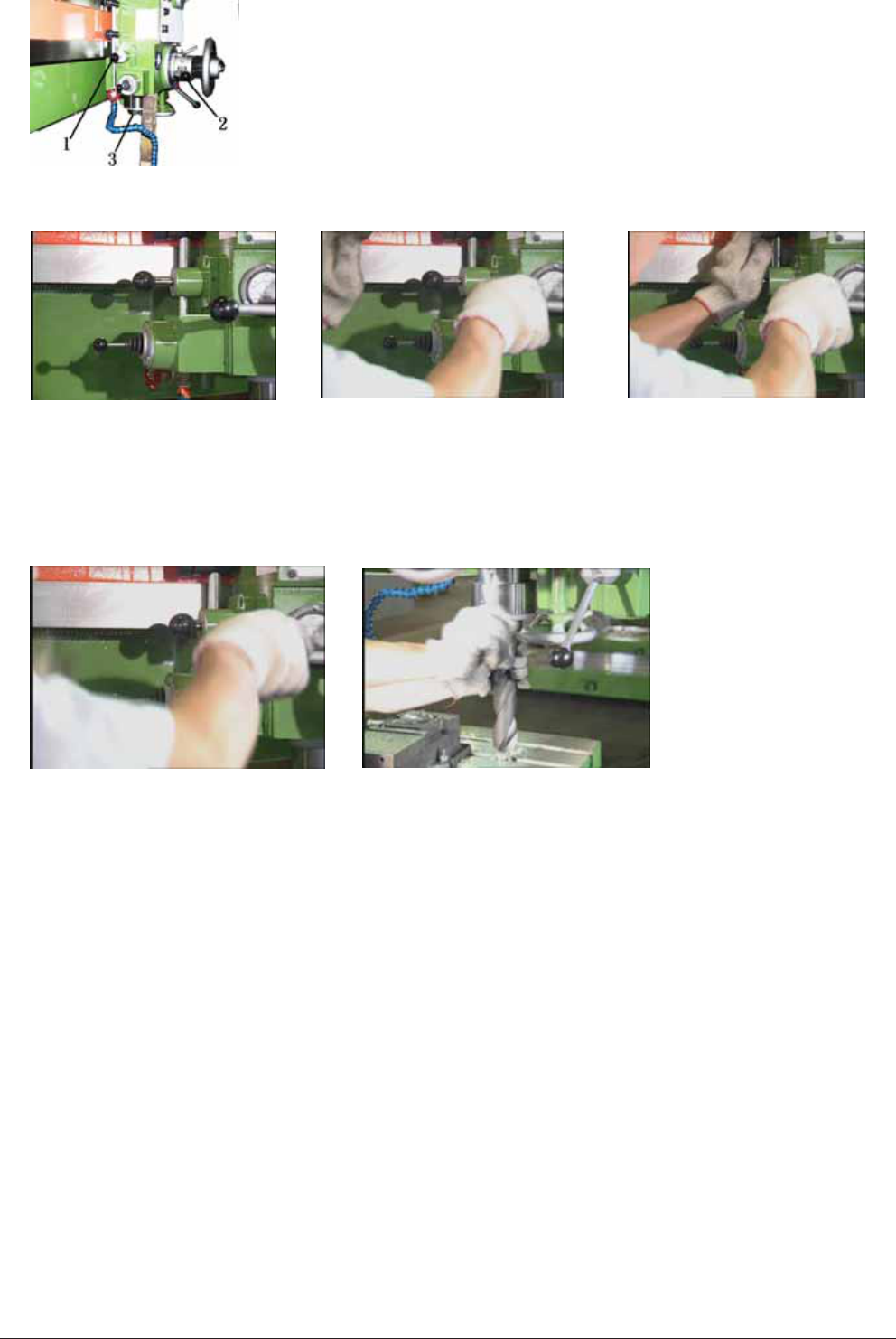
The way to use the releasing taper handle head and clamp
(
only applicable for TPR-)
1 The lever for releasing the dr
2 The feeding lever
3 The spindle
To dismantle as follows:
Step 1. Stand at th
of the machine.
Step 2 Grasp the feeding lever
using right hand and
release the spindle to its
utmost position.
Step 3. Press down the bit
releasing lever using left
hand.
Step 4. Keep grasping the drilling bit using left hand and rotate the feeding
lever counter clockwise until the
Assemble the drill bit head and the drill bit clamp as the following:
a. Move away the drilling bi
b. Power off.
c. Put on gloves.
d. Insert a thi
e.
Rotate the feed trip lever clockwise and have the spindle descend about
150 to 200 mm. As fi
f.
Rotate the revolving sh
hole of releasing drill
g. Place the drill bit clamp
h.
Place the drill bit and its clamp end into the revol
into the hole for relea
i.
Rotate the feed trip lever counter clockwise. Make the spindle descend till the drill bit and the
bottom end of the drill
it by confirming that t
Precaution:
The distance between th
mm.
5-12
The way to use the releasing taper handle head and clamp
(
only applicable for TPR-)
1 The lever for releasing the dr
2 The feeding lever
3 The spindle
To dismantle as follows:
Step 1. Stand at th
of the machine.
Step 2 Grasp the feeding lever
using right hand and
release the spindle to its
utmost position.
Step 3. Press down the bit
releasing lever using left
hand.
Step 4. Keep grasping the drilling bit using left hand and rotate the feeding
lever counter clockwise until the
Assemble the drill bit head and the drill bit clamp as the following:
a. Move away the drilling bit
b. Power off.
c. Put on gloves.
d. Insert a thi
e.
Rotate the feed trip lever clockwise and have the spindle descend about
150 to 200 mm. As fi
f.
Rotate the revolving sh
hole of releasing drill
g. Place the drill bit clamp
h.
Place the drill bit and its clamp end into the revol
into the hole for relea
i.
Rotate the feed trip lever counter clockwise. Make the spindle descend till the drill bit and the
bottom end of the drill
it by confirming that t
Precaution:
The distance between th
mm.