12-8
12
SET MODE
■ ACC set mode (continued)
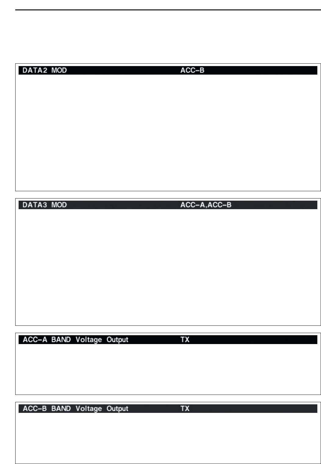
Selects the desired band for the operating frequency
band control signal output from [ACC2–B] (pin 4).
• MAIN : Outputs the band signal displayed in main
readout.
• SUB : Outputs the band signal displayed in sub
readout.
• TX : Outputs the band signal, that can be trans-
mitted. (default)
Selects the desired connector(s) for modulation input
when data 2 mode (D2) is in use.
• MIC : Use the signals from [MIC].
• ACC-A : Use the signals from [ACC1–A]
(pin 4).
• ACC-B : Use the signals from [ACC1–B]
(pin 4). (default)
• MIC,ACC-A : Use the signals from [MIC] and
[ACC1–A] (pin 4).
• MIC,ACC-B : Use the signals from [MIC] and
[ACC1–B] (pin 4).
• ACC-A,ACC–B : Use the signals from [ACC1–A]
and [ACC1–B] (pin 4).
• MIC,ACC-A,ACC–B
: Use the signals from [MIC],
[ACC1–A] and [ACC1–B] (pin 4).
• S/P DIF : Use the signals from [S/P DIF].
Selects the desired connector(s) for modulation input
when data 3 mode (D3) is in use.
• MIC : Use the signals from [MIC].
• ACC-A : Use the signals from [ACC1–A]
(pin 4).
• ACC-B : Use the signals from [ACC1–B]
(pin 4).
• MIC,ACC-A : Use the signals from [MIC] and
[ACC1–A] (pin 4).
• MIC,ACC-B : Use the signals from [MIC] and
[ACC1–B] (pin 4).
• ACC-A,ACC–B : Use the signals from [ACC1–A]
and [ACC1–B] (pin 4). (default)
• MIC,ACC-A,ACC–B
: Use the signals from [MIC],
[ACC1–A] and [ACC1–B] (pin 4).
• S/P DIF : Use the signals from [S/P DIF].
Selects the desired band for the operating frequency
band control signal output from [ACC2–A] (pin 4).
• MAIN : Outputs the band signal displayed in main
readout.
• SUB : Outputs the band signal displayed in sub
readout.
• TX : Outputs the band signal, that can be trans-
mitted. (default)