NOTE: When using with a notebook PC, be sure to connect between the projector and the notebook PC before turning on the power to the notebook PC. In most cases
signal cannot be output from RGB output unless the notebook PC is turned on after connecting with the projector.
NOTE:
* If the screen goes blank while using your remote control, it may be the result of the computer’s screen-saver or power management software.
* If you accidentally hit the POWER button on the remote control, wait 60 seconds and then press the POWER button again to resume.
NOTE: If using video, S-video, or audio cables, the cables should be 3 m (9.8 feet) or shorter.
For LT158:
When Viewing a DVI Digital Signal:
To project a DVI digital signal, be sure to connect the PC and the projector using the supplied DVI-D signal cable before turning on your PC or
projector. Turn on the projector first and select DVI (DIGITAL) from the source menu before turning on your PC.
Failure to do so many not activate the digital output of the graphics card resulting in no picture being displayed. Should this happen, restart your PC.
Do not disconnect the supplied DVI-D signal cable while the projector is running. If the signal cable has been disconnected and then re-connected,
an image may not be correctly displayed. Should this happen, restart your PC.
NOTE: Some personal computers or video cards may not display images correctly on the LT158.
To connect a DVI connector on your computer to LT158, attach the supplied DVI-D – DVI-D signal cable to the DVI connector on the projector. If you use a separately
sold DVI cable, images may not be correctly displayed.
NOTE: The DVI connector can accept a maximum resolution of 1024x768(XGA) when a DVI (DIGITAL) input is selected.
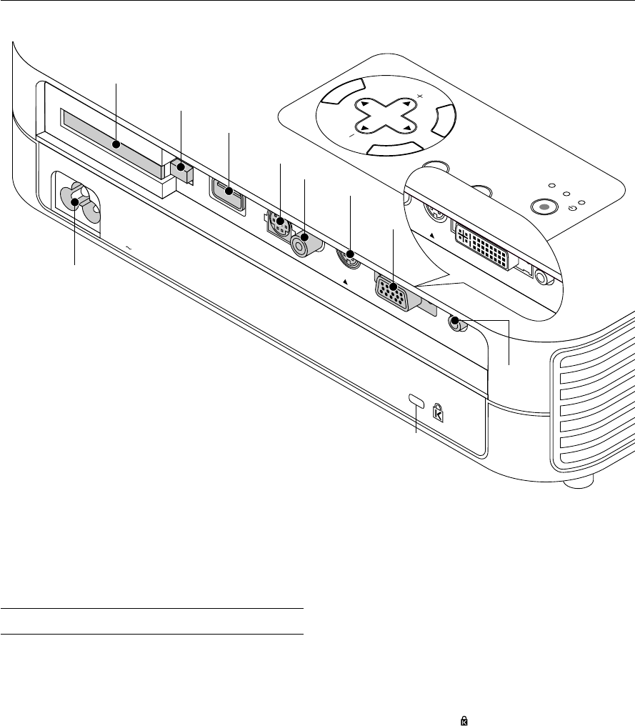
PC CONTROL
VIDEOS-VIDEORGBAUDIO
DVI
LT158
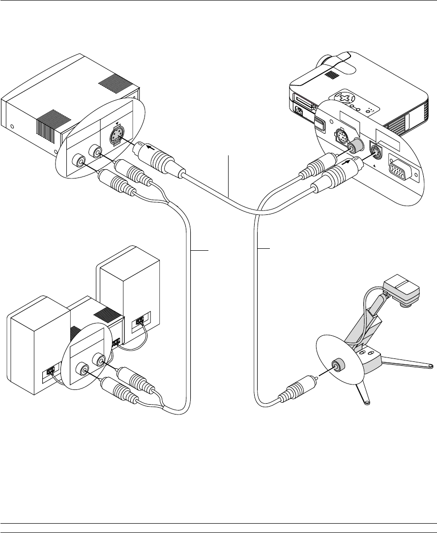
Wiring Diagram
RGB Signal cable (supplied)
To mini D-Sub 15-pin connector on
the projector. It is recommended that
you use a commercially available
distribution amplifier if connecting a
signal cable longer than the one
supplied.
For LT158:
DVI-D – DVI-D signal cable
(supplied) or DVI-A – VGA
signal cable (supplied)
To DVI connector on the projector.
IBM VGA or Compatibles
(Desktop type or notebook type)
DVD Player (with component output)
Component Video cable
RCA
ן
3 (not supplied)
Document Camera
To video, S-video, and audio
inputs on the projector.
VCR, DVD Player or
LaserDisc Player
Macintosh or Compatibles
(Desktop type or notebook type)
Optional 15-pin-to-RCA
(female)
ן
3 cable (ADP-CV1)
DVI-A – VGA signal
cable (supplied)
Gender changer
mini D-sub 15-pin F –
15-pin F (not supplied)
E – 19
C
C
A
R
D
P
C
C
O
N
T
R
O
L
V
I
D
E
O
D
V
I
-
D
U
S
B
S
-
V
I
D
E
O
A
U
D
I
O
M
E
N
U
E
N
T
E
R
C
A
N
C
E
L
SELECT
POWER
STATUS
O
N
/
STAND BY
SO
URCE
AUTO
ADJUST
PC CARD
ACCESS
A
C IN
E
O
D
V
I-D
S
-V
ID
E
O
A
U
D
IO
DVI
AUDIO
M
E
N
U
E
N
T
E
R
C
A
N
C
E
L
SE
LEC
T
P
OW
E
R
S
TATU
S
O
N
/
S
TA
ND B
Y
SO
UR
CE
A
U
T
O
ADJU
ST
PC
C
AR
D
A
CC
ES
S
A
C
IN
C
C
A
R
D
P
C
C
O
N
T
R
O
L
V
I
D
E
O
R
G
B
U
S
B
S
-
V
I
D
E
O
A
U
D
I
O
RGB
S-VIDEO
AUDIO
DEO
RGB INPUT
AUDIO
Audio cable (not supplied)
Connecting Your PC
Connecting your PC to your LT157 (XGA) projector will enable you to project your computer’s screen image for an impressive presentation.
To connect to a PC, simply:
1.Turn off the power to your projector and computer.
2.Use the supplied signal cable to connect your PC to the projector.
3.Turn on the projector and the computer.
4.If the projector goes blank after a period of inactivity, it may be caused by a screen saver installed on the computer you’ve connected to the
projector.
RGB signal cable (supplied)
To mini D-Sub 15-pin connector on the
projector. It is recommended that you
use a commercially available
distribution amplifier if connecting a
signal cable longer than the one
supplied .
Audio cable (not supplied)
DVI-D – DVI-D signal cable
(supplied)
To DVI connector on the projector.
DVI-A – VGA signal cable
(supplied)
IBM VGA or Compatibles
IBM VGA or Compatibles
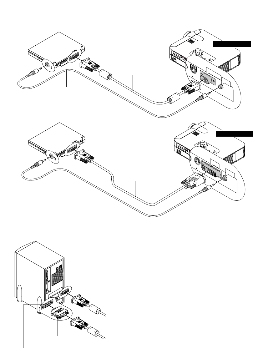
Connecting Your PC with a DVI Connector
You can connect your PC with a DVI output to your LT158 (XGA) projector.
When connecting a PC with a D-sub 15 pin analog connector, attach the supplied DVI-A – VGA signal cable to the D-sub 15 pin connector of your
PC.
To connect to a PC, simply:
1.Turn off the power to your projector and computer.
2. ① Use the supplied DVI-D–DVI-D signal cable to connect a DVI connector of your PC to the projector.
➁ To connect a PC with a mini D-sub 15 pin- mini D-sub 15 pin connector, attach the supplied DVI-A – VGA signal cable to the DVI connector on
the projector.
3.Turn on the projector and the computer.
4.If the projector goes blank after a period of inactivity, it may be caused by a screen saver installed on the computer you’ve connected to the
projector.
Mini D-Sub 15 pin connector
LT157
LT158
DVI connector ①
Mini D-Sub 15
pin connector ➁
Connection Option ① when using DVI output.
Connection Option
➁ when using mini D-Sub 15 pin output.
E – 20
C
C
A
R
D
P
C
C
O
N
T
R
O
L
V
I
D
E
O
D
V
I
-
D
U
S
B
S
-
V
I
D
E
O
A
U
D
I
O
M
E
N
U
E
N
T
E
R
C
A
N
C
E
L
S
E
L
E
C
T
P
O
W
E
R
S
T
A
T
U
S
O
N
/
S
T
A
N
D
B
Y
S
O
U
R
C
E
A
U
T
O
A
D
JU
S
T
P
C
C
A
R
D
A
C
C
E
S
S
A
C
IN
E
O
D
V
I
-
D
S
-
V
I
D
E
O
A
U
D
I
O
DVI
AUDIO
M
E
N
U
E
N
T
E
R
C
A
N
C
E
L
SELECT
P
OW
ER
STA
TUS
O
N
/
ST
AN
D BY
SO
UR
CE
AU
TO
ADJUST
P
C CARD
AC
C
ESS
AC
IN
C
C
A
R
D
P
C
C
O
N
T
R
O
L
V
I
D
E
O
R
G
B
U
S
B
S
-
V
I
D
E
O
A
U
D
I
O
RGB
S-VIDEO
AUDIO
DEO
RGB INPUT
AUDIO
RGB signal cable (supplied)
Audio cable (not supplied)
1
O
N
D
I
P
23
4
56
Pin adapter for Macintosh
(not supplied)
For older Macintosh, use a commercially
available pin adapter to connect to your
Mac's video port.
Connecting Your Macintosh Computer
Macintosh (Desktop type)
Audio cable (not supplied)
DVI-A – VGA signal cable
(supplied)
To connect to a Macintosh, simply:
1.Turn off the power to your projector and your Macintosh computer.
2.Use the supplied signal cable to connect your Macintosh computer to the
projector.
3.Turn on the projector and the Macintosh computer.
For LT158:
When connecting a Macintosh with a mini D-sub 15 pin analog connector,
attach the supplied DVI-A – VGA signal cable to the DVI connector on the
projector.
Macintosh (Notebook type)
LT157
LT158
E – 21
Connecting Your DVD Player
LT157
M
E
N
U
E
N
T
E
R
C
A
N
C
E
L
S
E
L
E
C
T
P
O
W
E
R
S
T
A
T
U
S
O
N
/
S
T
A
N
D
B
Y
S
O
U
R
C
E
A
U
T
O
A
D
J
U
S
T
P
C
C
A
R
D
A
C
C
E
S
S
A
C
I
N
C
C
A
R
D
P
C
C
O
N
T
R
O
L
V
I
D
E
O
R
G
B
U
S
B
S
-
V
I
D
E
O
A
U
D
I
O
R
G
B
S
-V
ID
E
O
A
U
D
IO
D
E
O
RGB INPUT
R
L
Y
C
b C
r
R
L
A
U
D
IO
C
om
ponent
A
U
D
IO
You can connect your projector to a DVD player with component out-
puts or Video output. To do so, simply:
1.Turn off the power to your projector and DVD player.
2. If your DVD player has the component video (Y/Cb/Cr) output, use a
commercially available component video cable (RCAן3) and the
optional 15-pin-to-RCA (female)ן3 cable to connect your DVD player
to the RGB INPUT connector on the projector.
For a DVD player without component video (Y/Cb/Cr) outputs, use
common RCA cables (not provided) to connect a composite VIDEO
output of the DVD player to the Video Input of the projector.
3.Turn on the projector and DVD player.
NOTE: Refer to your DVD player’s owner’s manual for more information about
your DVD player’s video output requirements,
Optional 15-pin-to-RCA (female)ן3
cable (ADP-CV1)
Audio cable
(not supplied)
DVD player
White
Red
Y
Cb
Cr
White
Red
Audio Equipment
Component video cable
RCAן3 (not supplied)
M
E
N
U
E
N
T
E
R
C
A
N
C
E
L
S
E
L
E
C
T
P
O
W
E
R
S
T
A
T
U
S
O
N
/
S
T
A
N
D
B
Y
S
O
U
R
C
E
A
U
T
O
A
D
J
U
S
T
P
C
C
A
R
D
A
C
C
E
S
S
A
C
I
N
C
C
A
R
D
P
C
C
O
N
T
R
O
L
V
I
D
E
O
R
G
B
U
S
B
S
-
V
I
D
E
O
A
U
D
I
O
E
O
D
V
I-D
S
-V
ID
E
O
A
U
D
IO
DVI-D
AUDIO
DVI-A – VGA
signal cable
(supplied)
LT158
For LT158:
Attach the supplied DVI-A–VGA cable to the DVI connector on your
projector.
To connect a DVD player (component), a commercially available gen-
der changer (Mini D-Sub 15p F-15p F) is required as well as ADP-
CV1.
Optional 15-pin-to-
RCA (female)ן3
cable
(ADP-CV1)
Gender changer
mini D-Sub 15p F
– 15p F
(not supplied)
E – 22
M
E
N
U
E
N
T
E
R
C
A
N
C
E
L
S
E
L
E
C
T
P
O
W
E
R
S
T
A
T
U
S
O
N
/
S
T
A
N
D
B
Y
S
O
U
R
C
E
A
U
T
O
A
D
J
U
S
T
P
C
C
A
R
D
A
C
C
E
S
S
A
C
I
N
C
C
A
R
D
P
C
C
O
N
T
R
O
L
V
I
D
E
O
R
G
B
U
S
B
S
-
V
I
D
E
O
A
U
D
I
O
R
G
B
S
-V
ID
E
O
P
C
C
O
N
T
R
O
L
V
ID
E
O
U
S
B
S-VIDEO
VIDEO
R L
S-VIDEO
AUDIO
R L
AUDIO
VIDEO
VCR/ Laser disc player
S-video cable (not supplied)
Audio equipment
Connecting Your VCR or Laser Disc Player
Use common RCA cables (not provided) to connect your VCR, laser disc player or document camera to your projector.
To make these connections, simply:
1.Turn off the power to the projector and VCR, laser disc player or document camera.
2. Connect one end of your RCA cable to the video output connector on the back of your VCR or laser disc player, connect the other end to the Video
input on your projector. Use an audio cable (not supplied) to connect the audio from your VCR or laser disc player to your audio equipment (if your
VCR or laser disc player has this capability). Be careful to keep your right and left channel connections correct for stereo sound.
3.Turn on the projector and the VCR or laser disc player.
NOTE: Refer to your VCR or laser disc player owner’s manual for more information about your equipment’s video output requirements.
Audio cable
(not supplied)
Video cable
(not supplied)
Document camera
E – 23
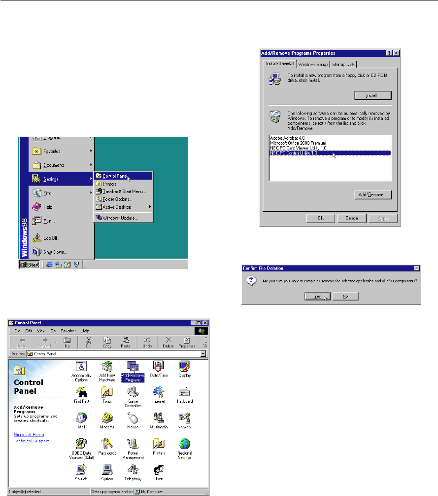
About Startup screen
(Menu Language Select screen)
When you first turn on the projector, you will get the Startup screen.
This screen gives you the opportunity to select one of the seven menu
languages: English, German, French, Itilan, Spanish,Swedish and Japa-
nese.
To select a menu language, follow these steps:
1.Use the Select ▲ or ▼ button to select one of the seven languages
for the menu.
2.Press the Enter button to execute the selection.
3.The Basic/Custom menu will be displayed in the language you
have selected.
To close the menu, press the Cancel button.
After this has been done, you can proceed to the advanced menu op-
eration.
If you want, you can select the menu language later. See “Language”
on page E-36.
E – 24
3. OPERATION
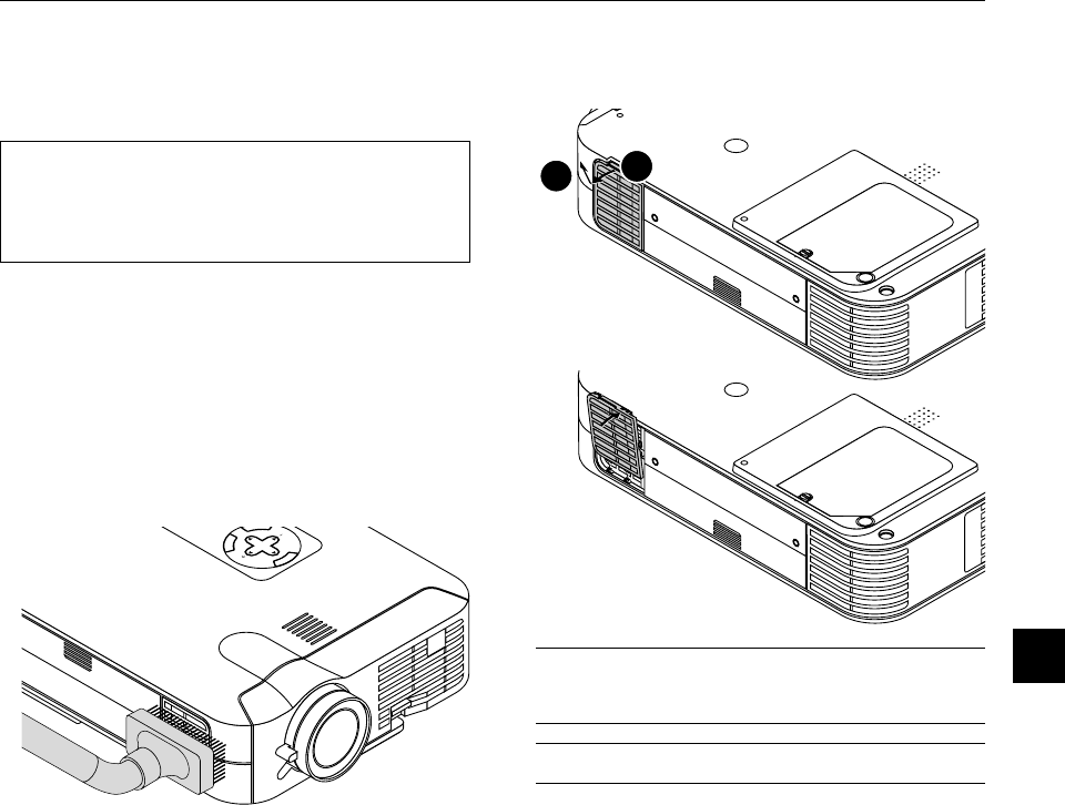
Connecting the Power Cable and Turning on the
Projector
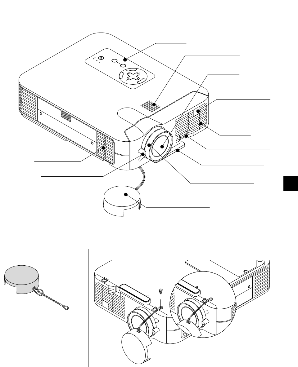
Before you turn on your projector, ensure that the computer or video
source is turned on and that your lens cap is removed.
1.Connect the supplied power cable to the projector.
M
E
N
U
E
N
T
E
R
C
A
N
C
E
L
S
E
L
E
C
T
P
O
W
E
R
S
T
A
T
U
S
O
N
/
S
T
A
N
D
B
Y
S
O
U
R
C
E
A
U
T
O
A
D
J
U
S
T
P
C
C
A
R
D
A
C
C
E
S
S
A
C
IN
C CARD
USB
PC CONTROL
VIDEOS-VIDEORGBAUDIO
Plug the supplied power cable in the wall outlet. The projector will
go into its standby mode and the power indicator will glow orange.
2.Turn on and off the Projector
M
E
N
U
OFF
VIDEO
AUTO ADJ.
S-VIDEORGB1RGB2
LASER
ON
POWER
Power ON button
M
E
N
E
N
T
E
R
C
A
N
C
E
L
SELECT
POWER
STATUS
ON
/
STAND BY
SOURCE
AUTO
ADJUST
PC CARD
ACCESS
P
C
C
O
N
T
R
O
L
V
ID
E
O
S
-V
ID
E
O
Power ON/STAND BY button
Indicator
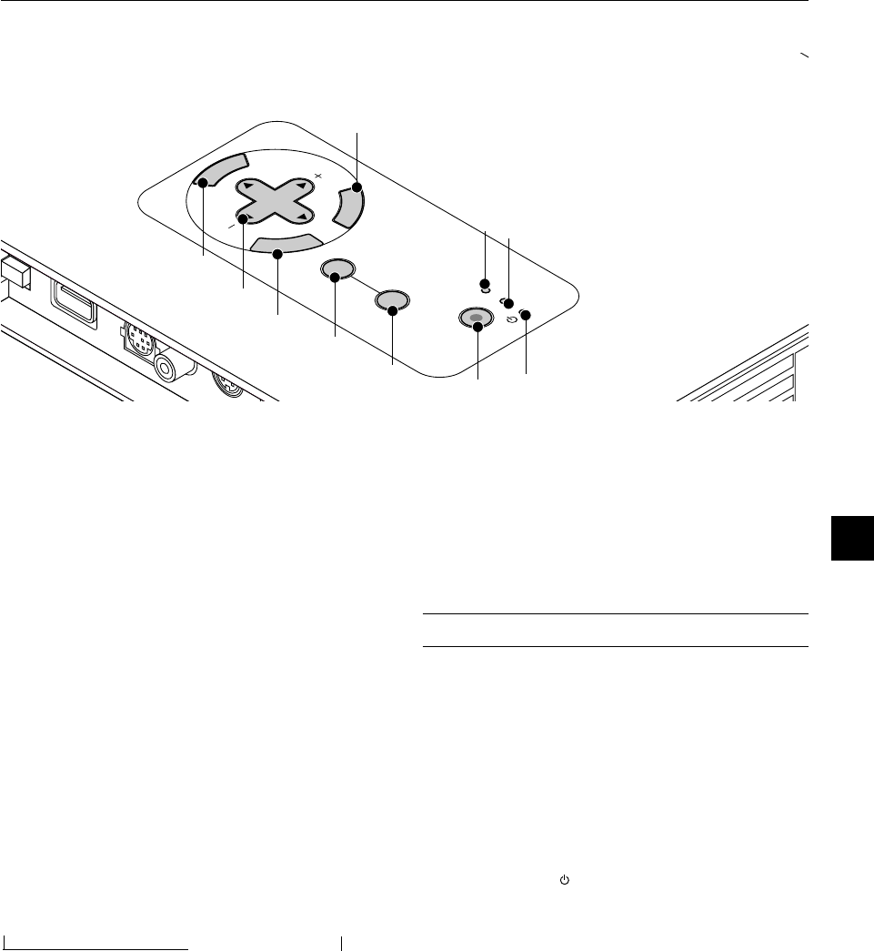
To turn on the projector:
Only after you press the “On” button on the remote control (“ON/
STAND BY” button on the projector cabinet) will the power indicator
turn to green and the projector become ready to use.
NOTE: To turn the projector on by plugging in the power cable, use the
menu and enable the “Auto Start” feature. (See page E-38.)
NOTE: Immediately after turning on the projector, screen flicker may occur.
This is not a fault. Wait 3 to 5 minutes until the lamp lighting is stabilized.
To turn off the projector:
First press the “off” button on the remote control (“ON/STAND BY”
button on the projector cabinet) for a minimum of two seconds. The
power indicator will glow orange. After the projector turns off, the
cooling fans keep operating for one minute.
NOTE: Do not disconnect the power cable during this time. Then, unplug
the power cable. The power indicator will go out.
Status of indicator light: turn on
POWER
STATUS
POWER
STATUS
ON
/
STAND BY
POWER
STATUS
Normal mode:
stand by
steady orange light
flashing green light
for one minute
steady green light
Eco mode:
POWER
STATUS
POWER
STATUS
POWER
STATUS
ON
/
STAND BY
stand by
steady orange light
flashing green light
for one minute
(Normal mode)
steady green light
(Eco mode)
Status of indicator light: turn off
ON
/
STAND BY
POWER
POWER
POWER
ON
steady green light
change to flashing
green light
steady orange light
cooling downstand by
Press a minimum
of two seconds.
E – 25
3.Adjust a Projected Image
Select the Computer or Video Source
VIDEOS-VIDEORGB1RGB2
PC CARD
E
N
T
E
R
C
A
N
C
E
L
SE
LECT
ON
/
STAND BY
SOURCE
AUTO
ADJUST
Press the Source button on the remote control or the projector cabinet
to select “Video” (VCR, document camera, or laser disc player), S-
Video”, “RGB” (computer or DVD with component output) [ “DVI digital”
, “DVI analog” (computer with DVI output: LT158 only)] or “PC Card
Viewer” (slides on a CompactFlash card) to display the image.
Or press the “Menu” button on the remote control or the cabinet and
use the menu to select your video source: “Video”, “S-Video”, “RGB
(DVI on LT158)” or “PC Card Viewer”.
NOTE: If no input signal is available, the projector will display a blue back-
ground (factory preset).
Adjust the Image Size and the Focus
Use the Zoom lever to fine adjust the image size on the screen
Use the Focus ring to obtain the best focus.
Place your projector on a flat
level surface and ensure that the
projector is square to the screen.
Lift the front edge of the projector to
center the image vertically.
Move the projector left to center
the image horizontally on the
screen.
Rotate the rear foot to make the
image square to the screen.
Use keystone correction for proper
adjustment.
E – 26
M
E
N
U
OFF
VIDEO
AUTO ADJ.
S-VIDEORGB1RGB2
LASER
ON
SC
POWER
[Poor picture]
[Normal picture]
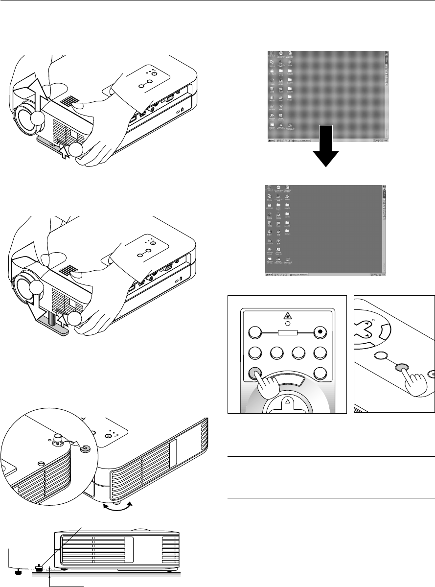
Adjust the Tilt Foot
1.Lift the front edge of the projector.
2.Press the Tilt button on the front of the projector to extend the ad-
justable tilt foot (maximum height).
M
E
N
U
E
N
T
E
R
C
A
N
C
E
L
S
E
L
E
C
T
P
O
W
E
R
S
T
A
T
U
S
O
N
/
S
T
A
N
D
B
Y
S
O
U
R
C
E
A
U
T
O
A
D
J
U
S
T
P
C
C
A
R
D
A
C
C
E
S
S
A
C
I
N
C
C
A
R
D
U
S
B
P
C
C
O
N
T
R
O
L
V
ID
E
O
S
-V
ID
E
O
R
G
B
A
U
D
IO
2
1
3.Press and hold the Tilt button.
4. Lower the front of the projector to the desired height and release the
button to lock the Adjustable tilt foot.
There is approximately 10 degrees of up and down adjustment for
the front of the projector.
Do not use the tilt-foot for purposes other than originally intended.
Misuses such as gripping the tilt-foot or hanging on the wall can cause
damage to the projector.
To fine-adjust the height of the rear foot, remove the spacer (black
rubber) and rotate the rear foot to the desired height.
*If the projected image does not appear square to the screen then
use keystone correction for proper adjustment.
Adjust the Image Using Auto Adjust
The Auto Adjust function automatically optimizes the image in RGB
mode.
E
N
T
E
R
C
A
N
C
E
L
SE
LECT
ON
/
STAND BY
SOURCE
AUTO
ADJUST
Press the Auto Adjust button to adjust Position-H/V and Pixel Clock/
Phase for an optimal picture. Some signals may not be displayed cor-
rectly or take time to switch between sources.
NOTE: For LT158
*The horizontal and vertical position adjustments to DVI digital signal are not
stored in memory on LT158.
*The Pixel Clock and Phase items are not available for a DVI digital signal on
LT158 (these adjustments are not necessary for this type of signal).
M
E
N
U
E
N
T
E
R
C
A
N
C
E
L
S
E
L
E
C
T
P
O
W
E
R
S
T
A
T
U
S
O
N
/
S
TA
N
D
B
Y
S
O
U
R
C
E
A
U
TO
A
D
JU
S
T
P
C
C
A
R
D
A
C
C
E
S
S
A
C
IN
C CARD
USB
PC C
ON
TRO
L
VIDEOS-VIDEO
RGBAUDIO
3
4
E
R
C
P
O
W
E
R
S
T
A
T
U
S
O
N
/
S
T
A
N
D
B
Y
S
O
U
R
C
E
A
U
T
O
A
D
J
U
S
T
P
C
C
A
R
D
A
C
C
E
S
S
GB
AUDIO
max.
min.
16mm
Spacer
Up
Down
E – 27
Source display
Each time the Source button is pressed, the input source will change
as follows:
→ RGB [“DVI (DIGITAL) → DVI (ANALOG)” on LT158] → Video
PC Card Viewer ← S-Video ←
If no input signal is present, the input will be skipped.
Press the Auto Adjust button to fine-tune the computer image or to
remove any vertical banding that might appear and to reduce video
noise, dot interference or cross talk (this is evident when part of your
image appears to be shimmering). This function adjusts the clock fre-
quencies that eliminate the horizontal banding in the image. This func-
tion also adjusts the clock phase to reduce video noise, dot interfer-
ence or cross talk. (This is evident when part of your image appears to
be shimmering.)
This adjustment may be necessary when you connect your computer
for the first time.
NOTE: The Auto Adjust function does not work for component signal.
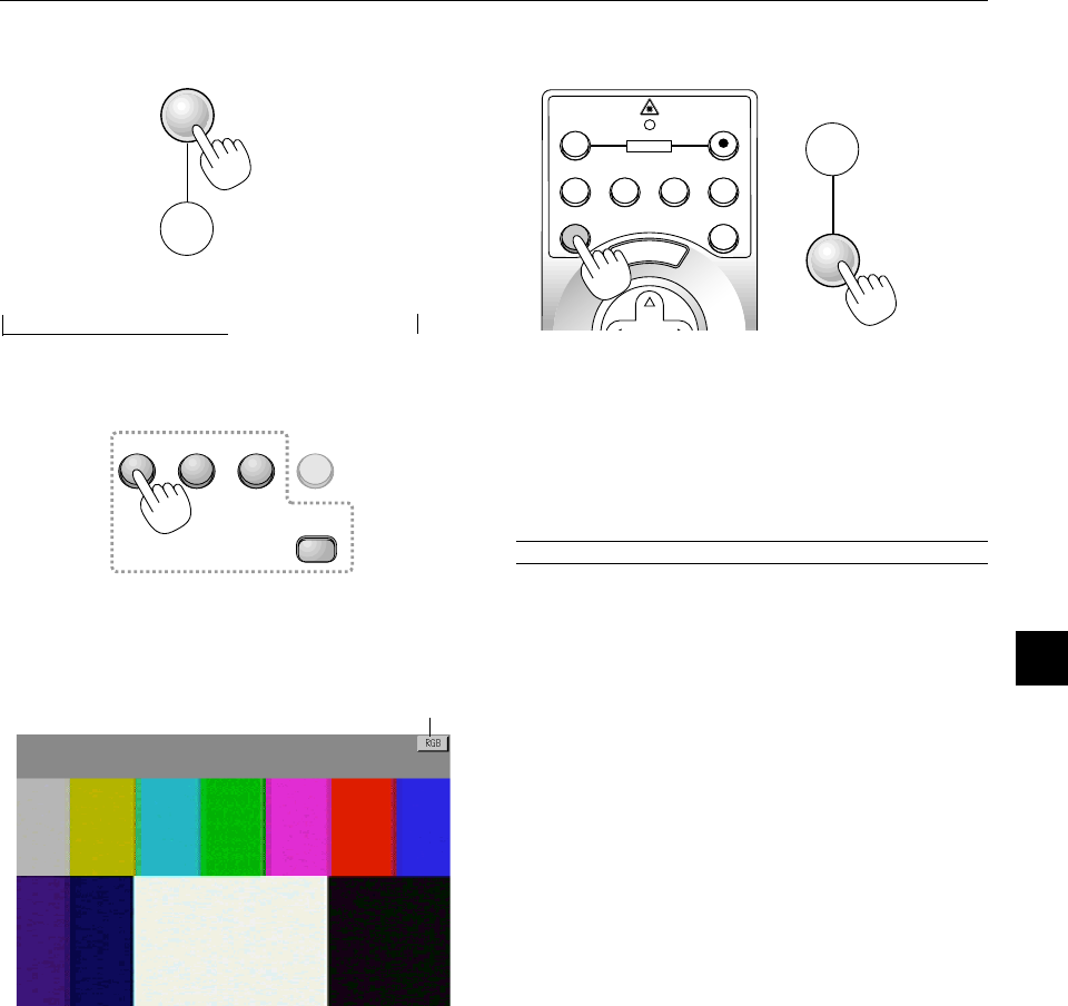
Basic Operation
Selecting the computer or video source:
Optimizing RGB image automatically
Press the Auto Adjust button to optimize an RGB image automatically.
SOURCE
AUTO
ADJUST
SOURCE
AUTO
ADJUST
M
E
N
U
OFF
VIDEO
AUTO ADJ.
S-VIDEORGB1RGB2
LASER
ON
SC
POWER
VIDEOS-VIDEORGB1RGB2
PC CARD
On LT158:
Press the RGB 1 button on the remote control to select DVI digital
signal and the RGB 2 button for DVI analog signal.
E – 28
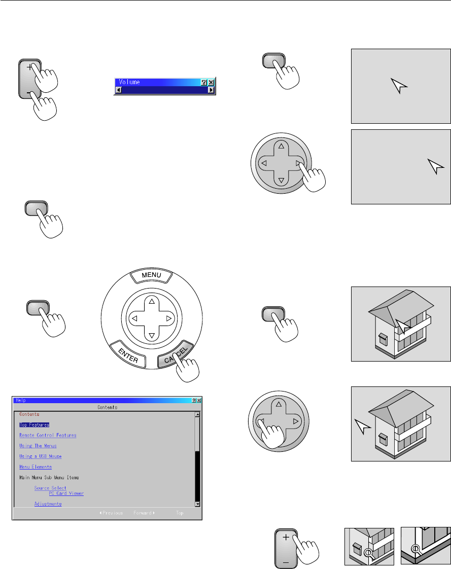
Volume control:
Sound level from the speaker on the projector can be adjusted.
increase volume
VOLUME
Volume bar
decrease volume
Turning off picture and sound:
Press the Picture Mute button to turn off the image and sound for a
short period of time. Press again to restore the image and sound.
PIC-MUTE
Getting Help about how to operate the projector:
You get the contents about Help.
Display Help
SELECT
Exit Help
Using Pointer
You can use one of eight pointers to draw your audience's attention to
the portion of a projected image you want.
Press the Pointer button to
display the pointer.
SELECT
Use the Select button to
move the pointer.
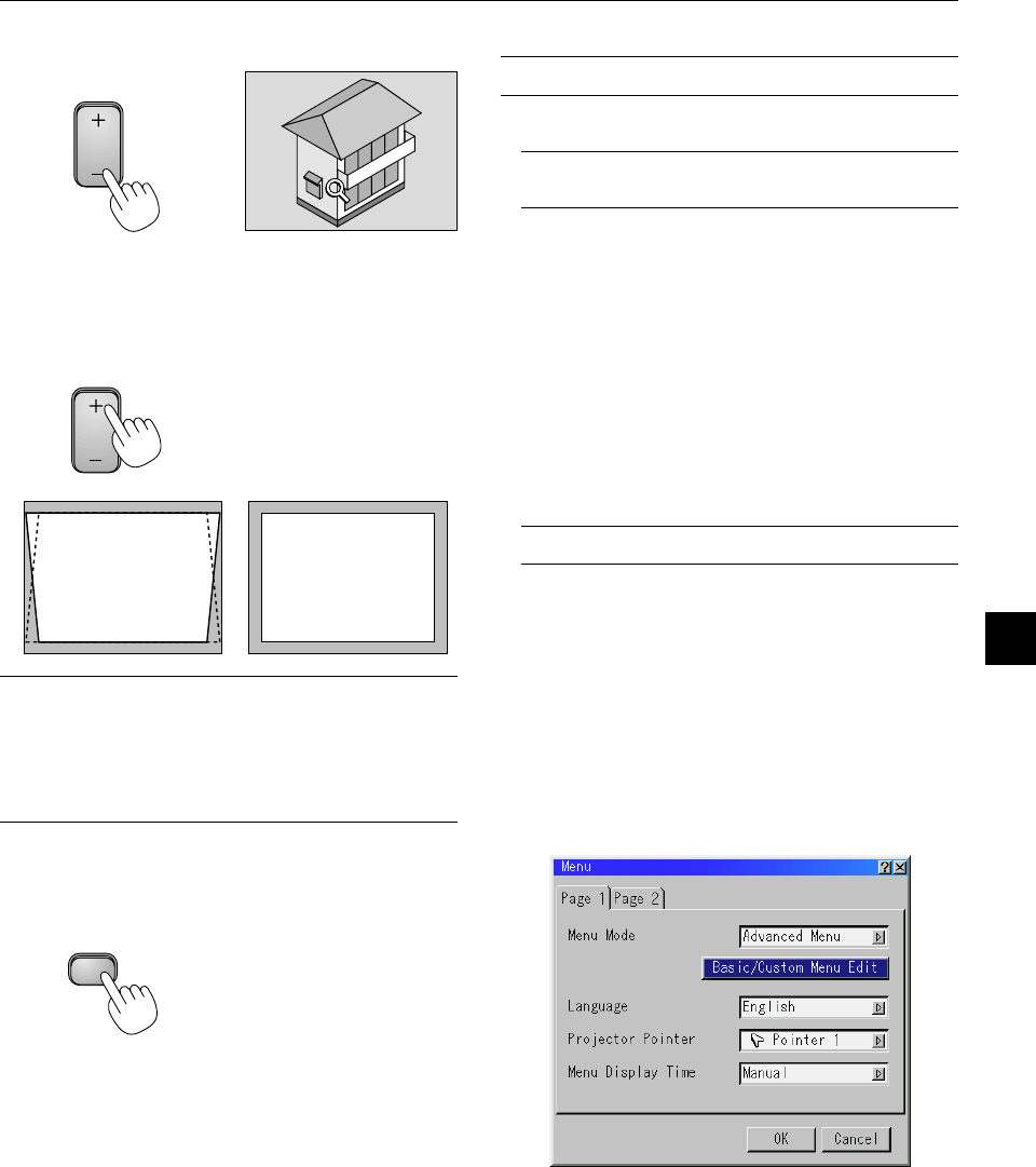
Enlarging and Moving a Picture
You can enlarge the area you want up to 400 percent.
To do so:
1.Press the Pointer button to display the pointer.
SELECT
2.Move the pointer to the area you want to enlarge.
3.Enlarge the selected area.
When the Magnify (+) button is pressed, the pointer is changed to
a magnifying glass. To move the magnifying glass, use the Seltct
button.
MAGNIFY
HELP
POINTER
POINTER
E – 29
4.Return the image to the original size.
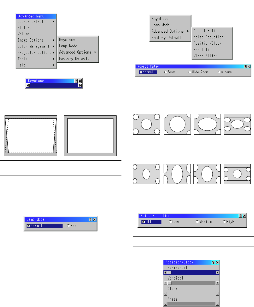
Correcting Keystone distortion
Press (+) or (-) to correct keystone (trapezoidal) distortion to make the
top or bottom of the screen longer or shorter so that the projected
image is rectangular.
KEYSTONE
NOTE: The maximum keystone angle that can be corrected is 40 degrees up-
ward and 20 degrees downward with the projector placed horizontally on the
ground plane.
Depending on the type of graphics being used, the picture may get blurred or
keystone correction may not be possible when excessive keystone correction
is used.
The idea is, the closer you are to native resolution, the better image you will
see.
Freezing a picture
Press the Freeze button to freeze a picture. Press again to resume
motion.
Keystone distortionNormal
MAGNIFY
FREEZE
Using the Menus
NOTE: The on-screen menu may not be displayed correctly while interlaced
motion video image is projected.
1.Press the “Menu” button on the remote control or projector cabi-
net to display the Main Menu.
NOTE: When using a USB mouse, click the mouse button to display the
main menu. For other operations, do the same way as you use your PC
mouse.
2.Press the ▲▼ buttons on the remote control or the projector cabi-
net to highlight the menu for the item you want to adjust or set.
3.Press the
ᮣ
button or the “Enter” button on the projector cabinet
or the “Left Click” button on the remote control to select a submenu
or item.
4.Adjust the level or turn the selected item on or off by using “Se-
lect”
ᮤ
or
ᮣ
buttons on the cabinet, or the “Mouse button” on the
remote control. The on-screen slide bar will show you the amount
of increase or decrease.
5.Changes are stored until you adjust it again.
ENTER.........Stores the setting or adjustments.
CANCEL..........
Return to the previous screen without storing settings or ad-
justments.
NOTE: You can close the main and sub menus simultaneously by pressing
the PJ button to cancel the Projector mode.
6.Repeat steps 2-5 to adjust an additional item, or press “Cancel”
on the projector cabinet or the remote control to quit the menu
display.
Customizing Basic/Custom Menu
The Basic/Custom menu can be customized to meet your requirements.
Selecting a menu item from the “Basic/Custom Menu Edit” list, allows
you to custom tailor the menu items to your needs.
1.Select “Basic/Custom Menu Edit” to display the “Basic/Custom
Menu Edit” screen.
E – 30
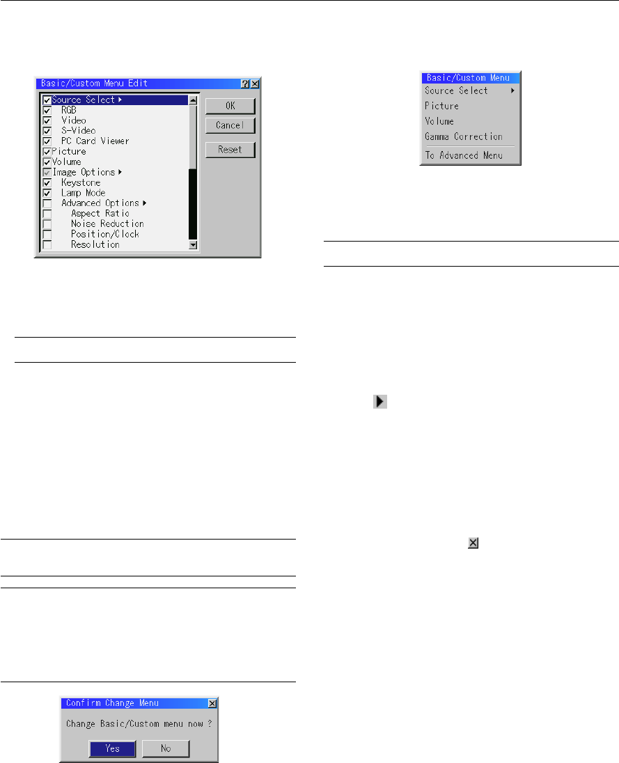
2.Use the ▲ or ▼ button to highlight your selection and press the
Enter button to place a check mark next to an option. This action
enables that feature.
Press the Enter button again to clear the check box.
If you select an item with a solid triangle
ᮣ
and press the Enter
button on the remote control or the projector cabinet, you can
enable all the items within that submenu.
Also you can turn on an item within the submenu without placing
a check mark on the main menu item.
NOTE: Up to 12 main menu items (within Basic/Custom Menu Edit, not
including submenu items) can be selected.
3.In order for the changes to take effect, use the
ᮤ
or
ᮣ
button on
the remote control or the projector cabinet to highlight “OK”,
then press the Enter button. To cancel the changes, use the ▲ or
▼ buttons to highlight “Cancel” and press the “Enter” button.
To return to the factory default, select “Reset” then press the “En-
ter” button.
The default Basic/Custom Menu items are:
Source Select (RGB [DVI (DIGITAL) / DVI (ANALOG) on LT158],
Video, S-Video and PC Card Viewer), Picture, Volume, Image Op-
tions (Keystone), Projector Options (Menu and Setup), Tools (Cap-
ture, PC Card Files and ChalkBoard) and Help (Contents and Infor-
mation)
NOTE: Once you have selected OK on the Basic/Custom Menu Edit screen, you
cannot cancel the changes on the Menu screen. However, you can re-edit the
menu items over again as described in the steps above.
NOTE: If the “Advanced Menu” item has been selected on the Menu mode, you
get the “Confirmation Change Menu” upon completion of “Basic/Custom Menu”
editing. In this case, selecting “Yes” then “Enter” will close all the menus and
apply the changes from the Advanced menu to the Basic/Custom Menu. If you
select “No” then “Enter” functions, then all menu items will return to the Ad-
vanced menu, but your changes will still be available within the “Basic/Custom
Menu” selection. To display the previously tailored Basic/Custom Menu, select
“Basic/Custom Menu” from the “Menu Mode”.
An item “To Advanced Menu” will be added to the bottom of the Basic/
Custom Menu.
Selecting this item and pressing the “Enter” button will display the “Ad-
vanced Menu” features.
Using a USB Mouse
Using a USB mouse gives you a smooth operation. A commercially
available USB mouse is required.
NOTE: There may be some brands of USB mouse that the projector does not
support.
Operate the Menus using the USB mouse:
Mouse Cursor:
When connecting a USB mouse to the projector, you get a mouse
cursor on the screen.
Unless you use your USB mouse within 10 seconds, the mouse
cursor disappears.
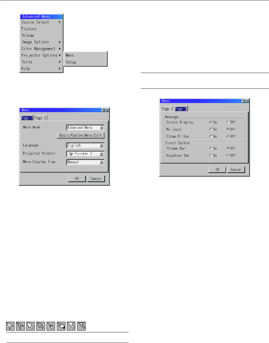
Menu Display:
Clicking with a mouse button displays the main menu.
Clicking
displays the pull-down menu.
To close the menu, click anywhere in the background.
Adjusting and Setting Display:
You can select a menu item and click with a mouse button to make
adjustments and setting.
Examples:
Click (or press and hold) the mouse button
ᮤ
or
ᮣ
to adjust the
brightness.
Or click and drag the mouse button on the slide bar horizontally to
adjust it.
To save the adjustments, click
. The display is closed.
If you click anywhere in the background while displaying adjust-
ment and setting menu or dialog box, you will get the main menu at
Libble nimmt den Missbrauch seiner Dienste sehr ernst. Wir setzen uns dafür ein, derartige Missbrauchsfälle gemäß den Gesetzen Ihres Heimatlandes zu behandeln. Wenn Sie eine Meldung übermitteln, überprüfen wir Ihre Informationen und ergreifen entsprechende Maßnahmen. Wir melden uns nur dann wieder bei Ihnen, wenn wir weitere Einzelheiten wissen müssen oder weitere Informationen für Sie haben.
Art des Missbrauchs:
Forenregeln
Um zu sinnvolle Fragen zu kommen halten Sie sich bitte an folgende Spielregeln:
Lesen Sie zuerst die Anleitung;
Schauen Sie nach, ob die Frage bereits gestellt wurde;
Stellen Sie die Frage so deutlich wie nur einigermaßen möglich;
Erwähnen Sie was Sie bereits versucht haben um das Problem zu lösen;
Ist Ihr Problem von einem Besucher gelöst dann lassen Sie ihn / sie wissen in diesem Forum;
Falls Sie reagieren möchten, so verwenden Sie bitte das Antworten- Formular;
Da ihre Frage für alle Besucher sichtbar ist, sollten Sie lieber keine persönliche Daten erwähnen.
Neu registrieren
Registrieren auf E - Mails für Nec LT158 wenn:
neue Frage gestellt werden
neue Handbücher vorhanden sind
Sie erhalten eine E-Mail, um sich für eine oder beide Optionen anzumelden.
Das Handbuch wird per E-Mail gesendet. Überprüfen Sie ihre E-Mail.
Wenn Sie innerhalb von 15 Minuten keine E-Mail mit dem Handbuch erhalten haben, kann es sein, dass Sie eine falsche E-Mail-Adresse eingegeben haben oder dass Ihr ISP eine maximale Größe eingestellt hat, um E-Mails zu erhalten, die kleiner als die Größe des Handbuchs sind.
Ihre Frage wurde zu diesem Forum hinzugefügt
Möchten Sie eine E-Mail erhalten, wenn neue Antworten und Fragen veröffentlicht werden? Geben Sie bitte Ihre Email-Adresse ein.