ing technology - an extremely accurate image compression technol-
ogy - offers a crisp image with UXGA (16001200) resolution*
2
.
•Supports most IBM VGA, SVGA, XGA, SXGA/UXGA(with Advanced
AccuBlend)*
2
, Macintosh, component signal (YCbCr / YPbPr) or any
other RGB signals within a horizontal frequency range of 15 to 100
kHz and a vertical frequency range of 50 to 120 Hz. This includes
NTSC, PAL, PAL60, SECAM and NTSC4.43 standard video signals.
NOTE: Composite video standards are as follows:
NTSC: U.S. TV standard for video in U.S. and Canada.
PAL: TV standard used in Western Europe.
PAL60: TV standard used for NTSC playback on PAL TVs.
SECAM: TV standard used in France and Eastern Europe.
NTSC4.43: TV standard used in Middle East countries.
•The supplied remote control can be used without a cable, and you
can even use the remote control and mouse adapter to operate your
PC or Macintosh mouse wirelessly from across the room with the
built-in remote mouse receiver.
•You can control the projector with a PC using the PC Control port*
3
.
•USB terminal allows USB mouse operation*
4
.
•The contemporary cabinet design is light, compact, easy to carry,
and complements any office, boardroom or auditorium.
•Eight pointers are available for your presentation.
*
1
Do not attempt to mount the projector on a ceiling yourself. The pro-
jector must be installed by qualified technicians in order to ensure
proper operation and reduce the risk of bodily injury. In addition, the
ceiling must be strong enough to support the projector and the in-
stallation must be in accordance with any local building codes. Please
consult your dealer for more information.
*
2
A UXGA (16001200) and SXGA (12801024) image are con-
verted to an XGA (1024768) crisp image with NEC Solutions’ Ad-
vanced AccuBlend.
*
3
The PC Control Utility 1.0 is required. This program is included on
the supplied CD-ROM.
*
4
The USB terminal meets the USB1.1 specification and accepts a
USB mouse only.
Getting Started
The fastest way to get started is to take your time and do everything
right the first time. Take a few minutes now to review the user’s manual.
This may save you time later on. At the beginning of each section of
the manual you’ll find an overview. If the section doesn’t apply, you can
skip it.
E – 6
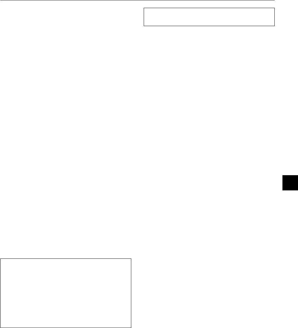
What’s in the Box?
Make sure your box contains everything listed. If any pieces are missing, contact your dealer.
Please save the original box and packing materials if you ever need to ship your MT1056 Projector.
M
E
N
U
E
N
T
E
R
C
A
N
C
E
L
SELECT
PO
W
ER
ST
ATU
S
O
N
/
STA
ND B
Y
SO
UR
CE
A
U
T
O
AD
JUS
T
A
C
IN
S
-
V
I
D
E
O
V
I
D
E
O
A
U
D
I
O
R
G
B
I
N
P
U
T
2
AUDIO
RGB INPUT 1
L
/
M
O
N
O
R
AUDIO
RGB MONITOR
OUTPUT
USB
PC-CARD
C CONTROL
MOUSE
OUT
REMO
CONTR
INPU
P
J
F
O
C
U
S
Z
O
O
M
V
O
L
.
S
H
I
F
T
H
E
L
P
P
O
IN
T
E
R
K
E
Y
S
T
O
N
E
M
A
G
N
IF
Y
F
R
E
E
Z
E
P
IC
-
M
U
T
E
O
F
F
V
I
D
E
O
A
U
T
O
A
D
J
.
S
-
V
I
D
E
O
R
G
B
1
R
G
B
2
L
A
S
E
R
P
O
W
E
R
O
N
P
C
C
A
R
D
S
L
I
D
E
F
O
L
D
E
R
S
L
ID
E
L
I
S
T
SELECT
Quick
Connect
Guide
User's
Manual
NEC MT1056 projector
Lens cap
(24FT7291)
String
(24C05051)
Batteries (AA2)
Power cable
(70810775 for North America)
(70800033 for Europe)
Serial cable
(73499390)
RGB signal cable
(15-Pin Mini D-Sub To 15-Pin Mini D-Sub connector)
(7N520001)
Mouse adapter
(For IBM PS/2)
(73499392)
Remote cable
(73499391)
CD-ROM
(7N950063)
Remote control
(7N900231)
Mouse adapter
(USB)
(7N520002)
Rivet
(24C04534)
(7N8P1311)
(7N8P1331)
E – 7
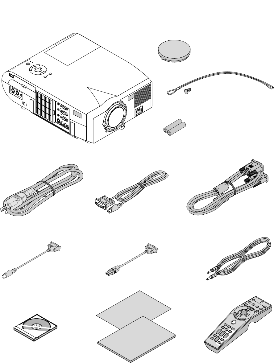
Getting to Know Your MT1056 Projector
M
E
N
U
E
N
T
E
R
C
A
N
C
E
L
SELECT
POWER
STATUS
ON
/
STAND BY
SOURCE
AUTO ADJUST
AC
IN
S
-
V
I
D
E
O
V
I
D
E
O
A
U
D
I
O
R
G
B
I
N
P
U
T
2
AUDIORGB INPUT 1
L
/
M
O
N
O
R
AUDIO
RGB MONITOR
OUTPUT
USB
PC-CARD
C CONTROL
MOUSE
OUT
REMO
CONTR
INPU
Zoom lever
Remote Sensor
Air-Filter
Lenscap
AC Input
Connect the supplied power cable’s three-
pin plug here.
Adjustable Tilt Foot
Lens
Ventilation (outlet)
Carrying Handle
Terminal Panel
Air Filter
Slot for Kensington
Micro saver Security
System
PC Card Slot
USB (Mouse)
Terminal
Controls
Remote Sensor
Front/Side Features
M
E
N
U
E
N
T
E
R
C
A
N
C
E
L
S
E
L
E
C
T
P
O
W
E
R
S
T
A
T
U
S
O
N
/
S
T
A
N
D
B
Y
S
O
U
R
C
E
A
U
T
O
A
D
J
U
S
T
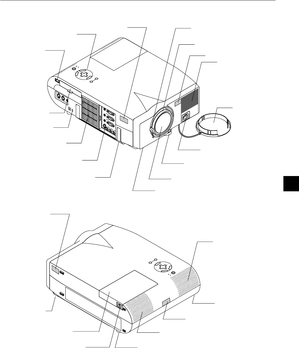
Rear/Side Features
Remote Sensor
One-touch Tilt Button
Lamp Cover
Lamp Cover Screw
Rear Foot
Built-In Stereo Speaker (1W)
Remote Sensor
Rear Foot
Built-In Stereo Speaker (1W)
Focus ring
E – 8
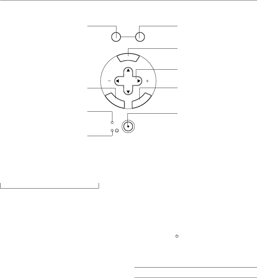
1. Source Button
Use this button to select a video source such as a PC, VCR, DVD
player or PC Card Viewer (PC card).
Each time this button is pressed, the input source will change as fol-
lows:
→ RGB1 → RGB2 → Video → S-Video → PC Card Viewer
If no input signal is present, the input will be skipped.
2. Auto Adjust Button (RGB only)
Use this button to adjust Position-H/V and Pixel Clock/Phase for an
optimal picture. Some signals may not be displayed correctly or take
time to switch between sources.
3. Menu Button
Displays the menu.
4. Select ▲▼
/ Volume (+) (-) Buttons
▲▼:Use these buttons to select the menu of the item you wish to
adjust.
When no menus appear, these buttons work as a volume con-
trol.
:Use these buttons to change the level of a selected menu item.
A press of the
button executes the selection.
When the menus or the Viewer tool bar is not displayed, these
buttons can be used to select a slide, or to move the cursor in
Folder List or Slide List.
When the pointer is displayed, these ▲▼
buttons move the pointer.
5. Enter Button
Executes your menu selection and activates items selected from the
menu.
Top Features
6. Cancel Button
Press this button to exit “Menus”. Press this button to return the adjust-
ments to the last condition while you are in the adjustment or setting
menu.
7. Status Indicator
When this is lit red (orange in Eco mode) continually, it’s warning you
that the projection lamp has exceeded 1500 hours (2500 hours in Eco
mode) of service. After this light appears, it is advisable to replace the
projection lamp as soon as possible. (See page E-47). In addition the
message “The lamp has reached the end of its usable life. Please re-
place the lamp.” appears continually until the lamp is replaced.
If this light blinks red rapidly, it indicates that the lamp cover is not
attached properly or the projector is overheated.
See the Power / Status Light Messages on page E-49 for more details.
8. Power Indicator (
)
When this indicator is green, the projector is on; when the indicator is
orange, it is in standby mode.
9. Power Button (ON / STAND BY)
Use this button to turn the power on and off when the power is sup-
plied and the projector is in standby mode.
NOTE: To turn off the projector, press and hold this button for a minimum of
two seconds.
M
E
N
U
E
N
T
E
R
C
A
N
C
E
L
SELECT
POWER
STATUS
ON
/
STAND BY
SOURCEAUTO ADJUST
1
5
7
8
2
3
4
6
9
E – 9
Terminal Panel Features
USB
123
4
1. USB Terminal
Connect a commercially available mouse that supports USB. You can
operate the menu or PC Card Viewer with the USB mouse via this
terminal.
Note that this terminal is not used with a computer and that there may
be some brands of USB mouse that the projector does not support.
2 PC Card Slot
Push up and open the cover to access this slot. Insert a PC card here.
3. PC Card Access Indicator
Lights while this indicator light shows that data is being.
4. PC Card Eject Button
Press to eject a PC card partially.
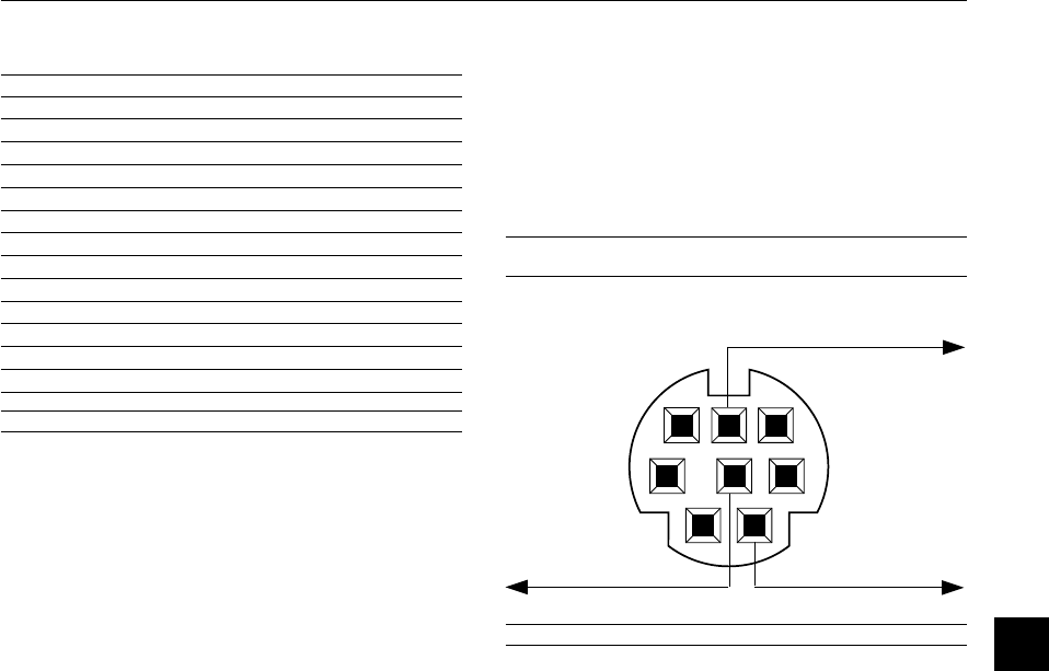
5. PC Control Port (Mini DIN 8 Pin)
Use this port to connect your PC to control your projector via a serial
cable. This enables you to use your PC and serial communication pro-
tocol to control the projector. The NEC optional serial cable is required
to use this port. Also PC Control Utility 1.0 included in the supplied CD-
ROM must be installed on your PC.
If you are writing your own program, typical PC control codes are on
page E-55.
A cap is put on the port at the factory. Remove the cap when using the
port.
6. Mouse Output Port (Mini DIN 8 Pin)
Use this port to operate your computer’s mouse functions from the
remote control.
7. Remote Control Input Jack
Connect your remote control cable here for wired operation.
8. Audio Monitor Output Mini Jack
Connect additional external speakers here to listen to audio coming
from your computer, Video or S- Video input.
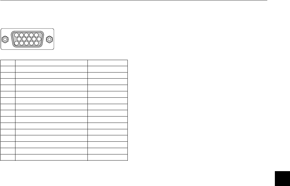
RGB Monitor Output Connector (Mini D-Sub 15 pin)
You can use this connector to loop your computer image to an external
monitor from the RGB input source.
9. RGB Audio Input 1 Connector
This is where you connect RGB audio output from a computer or an-
other RGB source.
RGB Input 1 Connector (Mini D-Sub 15 pin)
Connect your PC or other RGB equipment. Use the signal cable that’s
supplied to connect to a PC.
10. RGB Audio Input 2 Connector
This is where you connect RGB audio output from a computer or an-
other RGB source.
RGB Input 2 Connector (Mini D-Sub 15 pin)
Connect your PC or other RGB equipment. Use the signal cable that’s
supplied to connect to a PC.
11. S-Video Input Port
Here is where you connect the S-Video input from an external source
like a VCR.
12. Left Channel/Mono Audio Input Jack (RCA)
This is the left channel audio input for stereo sound coming from video
equipment or audio system. This also serves as your monaural audio
input. (Video and S-video only)
Right Channel Audio Input Jack (RCA)
This is the right channel audio input for stereo sound. (Video only)
NOTE: When using two Video sources simultaneously, the Left Channel Audio
Input jack is available for the S-Video source only and the Right Channel Audio
Input jack is available for the composite video source only.
13. Video Input
Connect a VCR, DVD player, laser disc player, or document camera
here to project video.
14. Built-in Security Slot (
)
This security slot supports the MicroSaver
®
Security System.
MicroSaver
®
is a registered trademark of Kensington Microware
Inc. The logo is trademarked and owned by Kensington Microware Inc.
PC CONTROL
REMOTE
CONTROL
INPUT
MOUSE
OUTPUT
5
6
7
M
E
N
U
RC
E
AUTO ADJUST
U
S
B
C
C
O
N
T
R
O
L
M
O
U
S
E
O
U
T
P
U
T
R
E
M
O
C
O
N
T
R
IN
P
U
P
C
-C
A
R
D
14
S-VIDEO
VIDEO
AUDIORGB INPUT 2
AUDIORGB INPUT 1
L
/
MONO
R
AUDIO
RGB MONITOR
OUTPUT
8
9
10
111213
E – 10
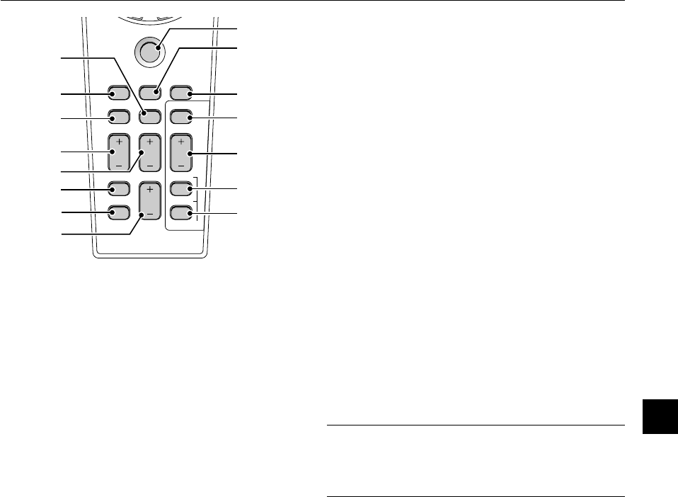
4. LED
Flashes when any button is pressed.
5. Power ON Button
If the main power is applied, you can use this button to turn your pro-
jector on.
P
J
FOCUS
ZOOM
VOL.
SHIFT
HELP
P
O
I
N
T
E
R
KEYSTONE
M
A
G
N
I
F
Y
F
R
E
E
Z
E
P
IC
-
M
U
T
E
P
C
C
A
R
D
SLIDE
F
O
L
D
E
R
S
L
I
D
E
LIST
OFF
VIDEO
AUTO ADJ.
S-VIDEO
RGB1
RGB2
LASER
ON
POWER
S
E
L
E
C
T
3
2
1
Remote Control Features
NOTE: If you are using a Macintosh computer, you can click either the right-
click or left-click button to activate the mouse.
1. Infrared Transmitter
Direct the remote control toward the remote sensor on the projector
cabinet.
2. Laser Pointer
Beams a laser light when “Laser” button is pressed.
3. Remote Jack
Connect your remote control cable here for wired operation.
M
E
N
U
E
N
T
E
R
C
A
N
C
E
L
PJ
OFF
VIDEO
AUTO ADJ.
S-VIDEORGB1RGB2
LASER
ON
SELECT
POWER
6
8
7
11
13
15
4
5
9
1
0
1
2
1
4
1
6
6. Power OFF Button
If the main power is applied, you can use this button to turn your pro-
jector off.
NOTE: To turn off the projector, press and hold the POWER OFF button for a
minimum of two seconds.
7. VIDEO Button
Press this button to select an NTSC, PAL, SECAM or NTSC4.43 com-
patible video source from a VCR, DVD player, laser disc player or docu-
ment camera.
8. S-VIDEO Button
Press this button to select an S-Video source from a VCR.
9. RGB 1 Button
Press this button to select a video source from a computer or compo-
nent equipment connected to your RGB 1 port.
10. RGB 2 Button
Press this button to select a video source from computer or compo-
nent equipment connected to your RGB 2 port.
11. AUTO ADJ Button
Use this button to adjust an RGB source for an optimal picture. Some
signals may not be displayed correctly or take time to switch between
sources.
12. LASER Button
Press and hold this button to activate the laser pointer. When lit, you
can use the laser to draw your audience’s attention to a red dot that
you can place on any object.
13. MENU Button
Displays the menu for various settings and adjustments.
14. SELECT (▲▼
) (Mouse) Button
When you are in the Computer mode, these buttons work as a com-
puter mouse.
When you are in the Projector mode, which is indicated by lighting the
PJ button:
▲▼
:Use these buttons to select the menu of the item you wish to
adjust.
:Use these buttons to change the level of a selected menu item.
A press of the
button executes the selection.
When the pointer is displayed, these
▲▼
buttons move the pointer.
15. ENTER (Left Click) Button
When you are in the Computer mode, this button works as the mouse
left button.
When this button is pressed and held for a minimum of 2 seconds, the
drag mode is set.
When you are in the Projector mode, which is indicated by lighting the
PJ button:
Use this button to enter your menu selection. It works the same way as
the “Enter” button on the cabinet.
16. CANCEL (Right Click) Button
When you are in the Computer mode, this button works as the mouse
right button.
When you are in the Projector mode, which is indicated by lighting the
PJ button:
Press this button to exit “Menus”. It works the same way as the “Can-
cel” button on the cabinet.
E – 11
PJ
FOCUSZOOM
VOLUME
SHIFT
HELP
POINTER
KEYSTONE
MAGNIFY
FREEZE
PIC-MUTE
PC CARD
SLIDE
FOLDER
SLIDE
LIST
1
7
1
9
2
0
2
8
2
9
3
0
31
22
18
21
23
24
25
26
27
17. PJ Button
Press this button to switch the Select, Cancel, and Enter buttons be-
tween the Projector mode (lit red) and the Computer mode. Press this
button or any one of the Power ON/OFF, Menu, Help, Pointer, Magnify,
PC Card, Folder List or Slide List buttons to switch to the Projector
mode and the PJ button lights red. To switch back to the Computer
mode, press the PJ button again.
18. FOCUS Button
Not available on this model.
19. ZOOM Button
Not available on this model.
20. SHIFT Button
Not available on this model.
21. HELP Button
Provides information about operation and adjustment procedures or
the set information for the current menu or adjustment during menu
operation.
22. POINTER Button
Press this button to display one of the eight pointers; press again to
hide the pointer. You can move your pointer icon to the area you want
on the screen using the Select button.
23. KEYSTONE (+) (–) Button
Press the (+) or (–) button to correct the keystone (trapezoidal) distor-
tion, and make the image square.
24. MAGNIFY (+) (–) Button
Use this button to adjust the image size up to 400%.
When the pointer is displayed, the image is magnified about the center
of the pointer. When the pointer is not displayed, the image is magni-
fied about the center of the screen.
When the image is magnified, the pointer is changed to the magnifying
icon.
25. FREEZE Button
This button will freeze a picture. Press again to resume motion.
26. PICTURE MUTE Button
This button turns off the image and sound for a short period of time.
Press again to restore the image and sound.
NOTE: When the menu is displayed, a press of this button mutes an
image and sound without turning off the menu.
27. VOLUME (+) (–) Button
Press (+) to increase the volume and (–) to decrease it.
28. PC CARD Button
Press this button to select the PC Card Viewer source.
29. SLIDE (+) (–) Button
Press (+) to select the next folder or slide and (–) to select the previous
folder or slide.
30. FOLDER LIST Button
Press this button to select PC Card Viewer source to display a list of
folders included in a CompactFlash card.
31. SLIDE LIST Button
Press this button to select PC Card Viewer source to display a list of
slides included in a CompactFlash card.
*NOTE: The default is the Computer mode, which allows you to use the Select,
Cancel, and Enter buttons as your computer mouse. When the POWER ON/
OFF, MENU, HELP, POINTER, MAGNIFY, PC CARD, FOLDER LIST, or SLIDE
LIST button is pressed, the PJ button lights red to indicate that you are in the
Projector mode. If no buttons are pressed within 10 seconds, the light goes out
and the Projector mode is canceled.
E – 12
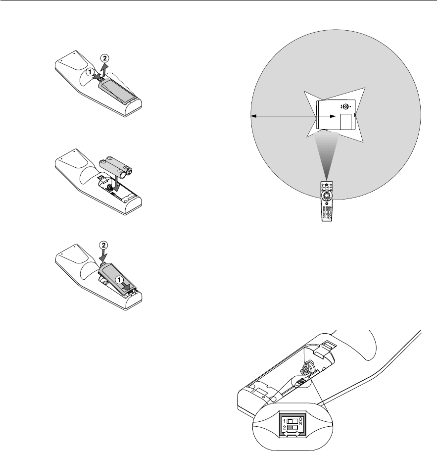
Operating Range
22
feet
/
7
m
Remote Control Precautions
•Handle the remote control carefully.
•If the remote control gets wet, wipe it dry immediately.
•Avoid excessive heat and humidity.
•If you will not be using the remote control for a long time, remove the
batteries.
•Do not place the batteries upside down.
•Do not look into the laser pointer while it is on.
•Do not point the laser beam at a person.
Remote Control Battery Installation
1.Press firmly and slide the battery cover off.
2.Remove both old batteries and install new ones (AA). Ensure that
you have the batteries’ polarity (+/–) aligned correctly.
3.Slip the cover back over the batteries until it snaps into place.
Do not mix different types of batteries or new and old batteries.
Note on Remote Control Operation:
Pressing and holding the Select (▲, ▼,
,
)/ Mouse button while
installing new batteries may cause malfunction or no operation.
Should this happen, remove the batteries and then install them again
without touching the Select/Mouse button.
Setting the function switch
ON
OFF
There are two switches on the bottom of the battery case: an appli-
cable projector selector switch (1) and laser enable/disable switch (2).
Check the projector being used and decide whether to enable or dis-
able laser, then set these switches as necessary using the tip of a thin
ball-point pen.
On this model, an applicable projector selector switch (1) is not used.
Switch (2)
On: Enabled (the laser lights when the LASER button is pressed) [Fac-
tory default]
Off: Disabled (the laser does not light even when the LASER button is
pressed)
Disable the laser when using in an environment in which the unit is
accessible to children.
E – 13
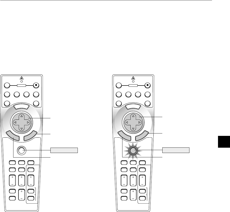
Switching operation mode between computer and projector
The three shaded buttons shown on the drawing work as a computer mouse in the Computer mode.
In the Computer mode the PJ button is not lit.
•When the MENU button is pressed, the PJ button lights red to indicate that you are in the Projector mode, which allows the projector menu
operation using the three buttons.
•When the POINTER button is pressed, the PJ button lights red to indicate that you are in the Projector mode and that the SELECT▲, ▼,
,
button works as a moving button for the POINTER or magnified image.
•If no buttons are pressed within 10 seconds, the PJ button’s light goes out to indicate that you are in the Computer mode. To enable the projector
menu operation again, press the PJ button to light red. To move the pointer or a magnified image again, turn off the pointer and then turn on the
pointer (press the POINTER button two times).
•When the PJ button is lit, if you want to use the mouse function immediately, press the PJ button to return to the Computer mode (not lit).
Works as the Select
button on the projector.
M
E
N
U
E
N
T
E
R
C
A
N
C
E
L
PJ
FOCUSZOOM
OFF
VIDEO
AUTO ADJ.
S-VIDEORGB1RGB2
LASER
ON
VOLUME
SHIFT
HELP
POINTER
KEYSTONE
MAGNIFY
FREEZE
PIC-MUTE
PC CARD
SLIDE
FOLDER
SLIDE
LIST
SELECT
POWER
M
E
N
U
E
N
T
E
R
C
A
N
C
E
L
FOCUSZOOM
OFF
VIDEO
AUTO ADJ.
S-VIDEORGB1RGB2
LASER
ON
VOLUME
SHIFT
HELP
POINTER
KEYSTONE
MAGNIFY
FREEZE
PIC-MUTE
PC CARD
SLIDE
FOLDER
SLIDE
LIST
SELECT
POWER
PJ
Not lit
Works as a mouse for your
computer.
Works as a right-click button
for your computer.
Works as a left-click button for
your computer.
Lit red
Works as the Enter
button on the projector.
Works as the Cancel
button on the projector.
During Computer mode:
During Computer mode by pressing the ENTER button for 2 seconds
or more then releasing, the drag mode is set and the drag operation
can be performed simply by pressing the SELECT (▲, ▼,
,
) (mouse)
button. To cancel the drag mode, press the ENTER (left click) button
again or press the CANCEL (right click) button.
E – 14
2. INSTALLATION
This section describes how to set up your MT1056 projector and how
to connect video and audio sources.
Setting up Your Projector
Your MT1056 Projector is simple to set up and use. But before you get
started, you must first:
1.Determine the image size.
2.Set up a screen or select a non-glossy white wall onto which you
can project your image.
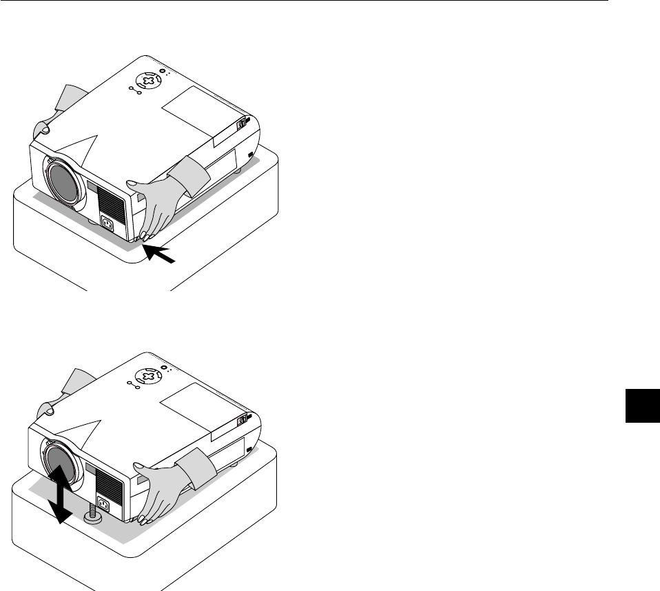
Carrying the Projector: Always carry your projector by the handle.
Ensure that the power cable and any other cables connecting to video
sources are disconnected before moving the projector.
When moving the projector or when it is not in use, cover the lens with
the lens cap.
Carrying handle
M
E
N
U
E
N
T
E
R
C
A
N
C
E
L
SELECT
POWER
STATUS
ON
/
OFF
SOURCE
AUTO ADJUST
U
S
B
AC IN
Attaching the lens cap to the bottom of the projector
with the supplied string and rivet.
Selecting a Location
The further your projector is from the screen or wall, the larger the
image. The minimum size the image can be is approximately 30" (0.76
m) measured diagonally when the projector is roughly 4.3 feet (1.3 m)
from the wall or screen. The largest the image can be is 300" (7.6 m)
when the projector is about 36.9 feet (11.3 m) from the wall or screen.
Using a Tabletop or Cart
1.Place your projector on a flat level surface at the optimal dis-
tance from the screen or wall so you realize the size image you
want.
(Avoid having bright room lighting or sun light directly on the screen
or wall where you’ll be projecting the image.)
2.Connect the power cable, remove the lens cap and turn the pro-
jector on.
(If no input signal is available, the projector will display a
background image.)
3.Ensure that the projector is square to the screen.
Lens cap
String
4.Move the projector left or right to center the image horizontally
on the screen.
5.To center the image vertically, lift the front edge of the projector
and press the One-Touch Tilt button on the front-left side of the
projector to release the Front Adjustable foot.
Top view
Screen
(There is approximately 10 degrees of up and down adjustment for the
front of the projector.)
6.If the projected image does not appear square to the screen then
use keystone correction for proper adjustment.
7.Adjust the size of the image using the Zoom lever on the lens.
Side view
Screen
A
C
IN
Rivet
E – 15
M
E
N
U
E
N
T
E
R
C
A
N
C
E
L
SELECT
POWER
STATUS
ON
/
OFF
SOURCE
AUTO ADJUST
AC IN
M
E
N
U
E
N
T
E
R
C
A
N
C
E
L
SE
LE
C
T
P
O
W
E
R
S
T
A
TU
S
O
N
/
O
FF
S
O
U
RC
E
A
U
TO
A
D
JU
S
T
A
C
IN
Adjusting the Tilt Foot
Press and hold the Tilt button on the left side of the projector.
Lift the front edge of the projector to the height you want, and release
the button to lock the Adjustable Tilt Foot.
To fine-tune the image’s position vertically on the screen, rotate the
foot. Each of the rear feet height can be changed up to 0.6" (4mm).
E – 16
Screen and Projection Distance
The following shows the proper relative positions of the projector and screen. Refer to the table to determine the position of installation.
558.8 (W
)
419.1 (H) / 220 (W
)
165 (H)
W
IDE : 300"
609.6 (W
)
457.2 (H) / 240 (W
)
180 (H)
406.4 (W
)
304.8 (H) / 160 (W
)
120 (H)
487.7 (W
)
365.8 (H) / 192 (W
)
144 (H)
304.8 (W
)
228.6 (H) / 120 (W
)
90 (H)
243.8 (W
)
182.9 (H) / 96 (W
)
72 (H)
203.2 (W
)
152.4 (H) / 80 (W
)
60 (H)
162.6 (W
)
121.9 (H) / 64 (W
)
48 (H)
121.9 (W
)
91.4 (H) / 48 (W
)
36 (H)
81.3 (W
)
61.0 (H) / 32 (W
)
24 (H)
67.1 (W
)
50.3 (H) / 26 (W
)
20 (H)
TELE: 30"
61.0 (W
)
45.7 (H) / 24 (W
)
18 (H)
Screen size (Unit: cm/inch)
Lens center
Screen
Distance (Unit: m/feet)
60
"
80
"
100
"
120
"
150
"
200
"
240
"
275
"
40
"
33"
1.3/4.3
1.6/5.2
2.4/7.9
3.2/10.5
4.1/13.4
4.9/16.1
6.2/20.2
8.2/27.0
9.9/32.5
11.3/36.9
Throw distance
E – 17
Ceiling Installation
Distance Chart
B=Vertical distance between lens center and screen
center
C=Throw distance
D=Vertical distance between lens center and screen
bottom (screen top for ceiling installation)
NOTE: Distances may vary +/–5%.
10.5
10.3
10.1
10.1
10.0
10.0
10.0
10.0
9.9
9.9
9.9
9.8
9.8
9.8
9.8
DiagonalWidthHeightwidetelephotowidetelephoto
B
C
Screen Size
Dα
30
762
40
1016
60
1524
67
1701.8
72
1828.8
84
2133.6
90
2286
100
2540
120
3048
150
3810
180
4572
210
5334
240
6096
270
6858
300
7620
inch
mm
inch
mm
inch
mm
inch
mm
inch
mm
inch
mm
inch
mm
inch
mm
inch
mm
inch
mm
inch
mm
inch
mm
inch
mm
inch
mm
inch
mm
24
609.6
32
812.8
48
1219.2
53.6
1361.44
57.6
1463.04
67.2
1706.88
72
1828.8
80
2032
96
2438.4
120
3048
144
3657.6
168
4267.2
192
4876.8
216
5486.4
240
6096
18
457.2
24
609.6
36
914.4
40.2
1021.08
43.2
1097.28
50.4
1280.16
54
1371.6
60
1524
72
1828.8
90
2286
108
2743.2
126
3200.4
144
3657.6
162
4114.8
180
4572
inch
mm
inch
mm
inch
mm
inch
mm
inch
mm
inch
mm
inch
mm
inch
mm
inch
mm
inch
mm
inch
mm
inch
mm
inch
mm
inch
mm
inch
mm
inch
mm
inch
mm
inch
mm
inch
mm
inch
mm
inch
mm
inch
mm
inch
mm
inch
mm
inch
mm
inch
mm
inch
mm
inch
mm
inch
mm
inch
mm
7.7
194.6
10.2
259.5
15.3
389.2
17.1
434.7
18.4
467.1
21.5
544.9
23.0
583.9
25.5
648.7
30.6
778.5
38.3
973.1
46.0
1167.7
53.6
1362.3
61.3
1557.0
69.0
1751.6
76.6
1946.2
inch
mm
inch
mm
inch
mm
inch
mm
inch
mm
inch
mm
inch
mm
inch
mm
inch
mm
inch
mm
inch
mm
inch
mm
inch
mm
inch
mm
inch
mm
41.4
1052.6
56.3
1430.3
86.1
2185.8
96.5
2450.2
103.9
2639.0
121.7
3092.3
130.7
3318.9
145.5
3696.6
175.3
4452.1
219.9
5585.2
264.5
6718.4
309.1
7851.5
353.7
8984.7
398.3
10117.8
443.0
11251.0
inch
mm
inch
mm
inch
mm
inch
mm
inch
mm
inch
mm
inch
mm
inch
mm
inch
mm
inch
mm
inch
mm
inch
mm
inch
mm
inch
mm
inch
mm
50.8
1290.5
68.6
1743.7
104.3
2649.9
116.8
2967.1
125.7
3193.7
147.1
3737.4
157.8
4009.3
175.7
4462.4
211.4
5368.7
264.9
6728.0
318.4
8087.4
371.9
9446.8
425.4
10806.2
479.0
12165.5
532.5
13524.9
inch
mm
inch
mm
inch
mm
inch
mm
inch
mm
inch
mm
inch
mm
inch
mm
inch
mm
inch
mm
inch
mm
inch
mm
inch
mm
inch
mm
inch
mm
1.3
34.0
1.8
45.3
2.7
68.0
3.0
75.9
3.2
81.5
3.7
95.1
4.0
101.9
4.5
113.3
5.4
135.9
6.7
169.9
8.0
203.9
9.4
237.9
10.7
271.8
12.0
305.8
13.4
339.8
inch
mm
inch
mm
inch
mm
inch
mm
inch
mm
inch
mm
inch
mm
inch
mm
inch
mm
inch
mm
inch
mm
inch
mm
inch
mm
inch
mm
inch
mm
degree
degree
degree
degree
degree
degree
degree
degree
degree
degree
degree
degree
degree
degree
degree
–
–
–
–
–
–
–
–
–
–
–
–
–
–
–
8.6
8.5
8.4
8.3
8.3
8.3
8.3
8.3
8.3
8.2
8.2
8.2
8.2
8.2
8.2
degree
degree
degree
degree
degree
degree
degree
degree
degree
degree
degree
degree
degree
degree
degree
–
–
–
–
–
–
–
–
–
–
–
–
–
–
–
If your projector is mounted on the ceiling and your image is upside down, use the “Menu” and “Select” buttons on your projector
cabinet or ▲▼ button on your remote control to correct the orientation. (See page E-36.)
Reflecting the Image
Using a mirror to reflect your projector’s image enables you to enjoy a much larger image. Contact your NEC dealer if you need a
mirror. If you’re using a mirror and your image is inverted, use the “Menu” and “Select” buttons on your projector cabinet or ▲▼ buttons
on your remote control to correct the orientation. (See page E-36.)
WARNING
•Installing your projector on the ceiling must be done
by a qualified technician. Contact your NEC dealer
for more information.
*Do not attempt to install the projector yourself.
•Only use your projector on a solid, level surface. If
the projector falls to the ground, you can be injured
and the projector severely damaged.
•Do not use the projector where temperatures vary
greatly. The projector must be used at temperatures
between 32°F (0°C) and 95°F (35°C).
•Do not expose the projector to moisture, dust, or
smoke. This will harm the screen image.
•Ensure that you have adequate ventilation around
your projector so heat can dissipate. Do not cover
the vents on the side or the front of the projector.
Throw Angle (α)
Throw Distance (C)
2.9" (79.5mm)
Lens Center
Screen top
Screen center
Screen Bottom
D
B
Projector Foot
Projector Foot
Screen top
2.9" (79.5mm)
Lens Center
Screen center
Screen Bottom
Throw Distance (C)
Throw Angle (α)
B
D
E – 18
PC CONTROL
REMOTE
CONTROL
INPUT
MOUSE
OUTPUT
S-VIDEO
VIDEO
AUDIORGB INPUT 2
AUDIORGB INPUT 1
L
/
MONO
R
AUDIO
RGB MONITOR
OUTPUT
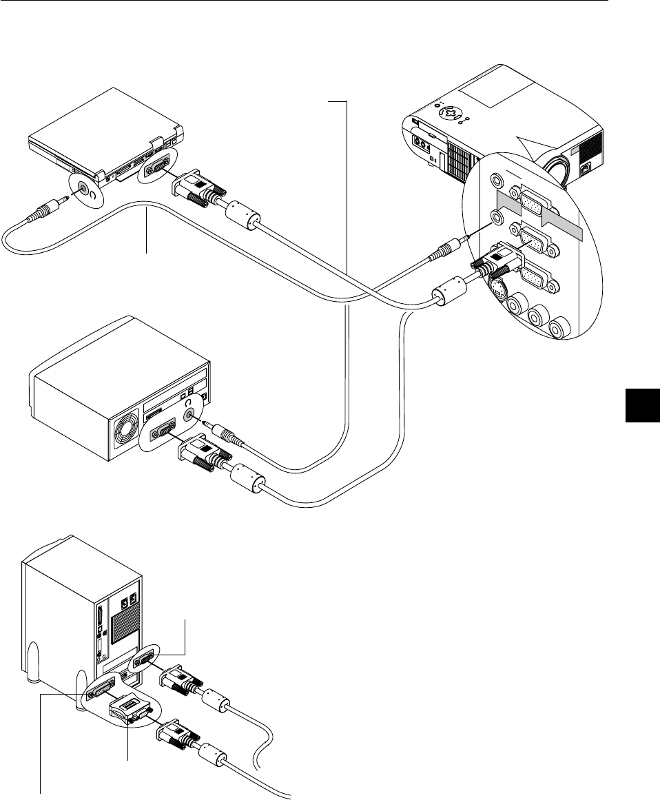
Wiring Diagram
NOTE: When using with a notebook PC, be sure to connect between the projec-
tor and the notebook PC before turning on the power to the notebook PC. In
most cases signal cannot be output from RGB output unless the notebook PC
is turned on after connecting with the projector.
NOTE: If using video, S-video, or audio cables, the cables should be 3 m (9.8
feet) or shorter.
Supplied serial cable
Supplied mouse adapter
(For USB)
Supplied mouse adapter
(For IBM PS/2 or USB)
Macintosh or Compatibles
(Desktop type or notebook type)
IBM VGA or Compatibles
(Desktop type or notebook type)
DVD Player (with component output)
Document Camera
To video, S-video, and audio
inputs on the projector.
VCR, DVD Player or LaserDisc Player
Monitor
Remote Control Guideline
1. Plug the supplied serial cable with the mouse output port of the pro-
jector into your computer’s mouse port and restart your computer to
gain remote mouse control.
2. When using the remote control’s built-in infrared mouse on a laptop
computer, the laptop’s mouse, trackball or trackpad will be disabled.
Disconnect the serial cable from the mouse output port and restart
your computer to regain trackball or trackpad mouse control.
3.If the screen goes blank while using your remote control, it may be
the result of the computer’s screen-saver or power management
software.
4. If you accidentally hit the OFF button on the remote control, wait one
full minute and then press the ON button to resume.
Signal cable (supplied)
To mini D-Sub 15-pin connector on the projector.
It is recommended that you use a commercially
available distribution amplifier if connecting a sig-
nal cable longer than the one supplied.
Component video cable
RCA3 (not supplied)
Optional 15-pin-to-RCA
(female)3 cable
(ADP-CV1)
E – 19
M
E
N
U
E
N
T
E
R
C
A
N
C
E
L
S
E
L
E
C
T
P
O
W
E
R
S
T
A
T
U
S
O
N
/
S
T
A
N
D
B
Y
S
O
U
R
C
E
A
U
T
O
A
D
J
U
S
T
A
C
I
N
S
-
V
I
D
E
O
V
I
D
E
O
A
U
D
I
O
R
G
B
I
N
P
U
T
2
A
U
D
I
O
R
G
B
I
N
P
U
T
1
L
/
M
O
N
O
R
A
U
D
I
O
R
G
B
M
O
N
I
T
O
R
O
U
T
P
U
T
U
S
B
P
C
-C
A
R
D
C
C
O
N
T
R
O
L
M
O
U
S
E
O
U
T
R
E
M
O
C
O
N
T
R
I
N
P
U
S-VIDEO
VIDEO
AUDIORGB INPUT 2
A
U
D
IO
R
G
B IN
P
U
T
1
L
/
MONO
R
A
U
D
IO
R
G
B
M
O
N
IT
O
R
O
U
TP
U
T
RGB INPUT
AUDIO
RGB signal cable (supplied)
To mini D-Sub 15-pin connector on the
projector. It is recommended that you
use a commercially available distribu-
tion amplifier if connecting a signal
cable longer than the one supplied.
IBM VGA or Compatibles (Desktop type)
Audio cable (not supplied)
Connecting Your PC or Macintosh Computer
IBM VGA or Compatibles (Notebook type)
or
Macintosh (Notebook type)
1
O
N
D
I
P
2
34
56
Pin adapter for Macintosh
(not supplied)
For older Macintosh, use a commercially
available pin adapter to connect to your
Mac’s video port.
The new Macintosh computer such as
G3 will have the 15 pin HD connec-
tor. The MT1056’s “Plug and Play”
data will be downloaded to the
Macintosh. Therefore, a Mac adapter
will not be necessary.
Macintosh (Desktop type)
Connecting your PC or Macintosh computer to your MT1056 (XGA)
projector will enable you to project your computer’s screen image for
an impressive presentation.
To connect to a PC or Macintosh, simply:
1. Turn off the power to your projector and computer.
2.Use the signal cable that’s supplied to connect your PC or Macintosh
computer to the projector.
3. Turn on the projector and the computer.
4.If the projector goes blank after a period of inactivity, it may be caused
by a screen saver installed on the computer you’ve connected to the
projector.
E – 20
M
E
N
U
E
N
T
E
R
C
A
N
C
E
L
S
E
L
E
C
T
P
O
W
E
R
S
T
A
T
U
S
O
N
/
S
T
A
N
D
B
Y
S
O
U
R
C
E
A
U
T
O
A
D
J
U
S
T
A
C
I
N
S
-
V
I
D
E
O
V
I
D
E
O
A
U
D
I
O
R
G
B
I
N
P
U
T
2
A
U
D
I
O
R
G
B
I
N
P
U
T
1
L
/
M
O
N
O
R
A
U
D
I
O
R
G
B
M
O
N
I
T
O
R
O
U
T
P
U
T
U
SB
P
C-CA
RD
C
C
O
N
T
R
O
L
M
O
U
S
E
O
U
T
R
E
M
O
C
O
N
T
R
I
N
P
U
N
T
R
O
L
M
O
U
S
E
O
U
T
P
U
T
R
E
M
O
C
O
N
T
R
IN
P
U
MOUSE
OUTPUT
Serial cable (supplied)
Macintosh with
USB Port
IBM PS/2
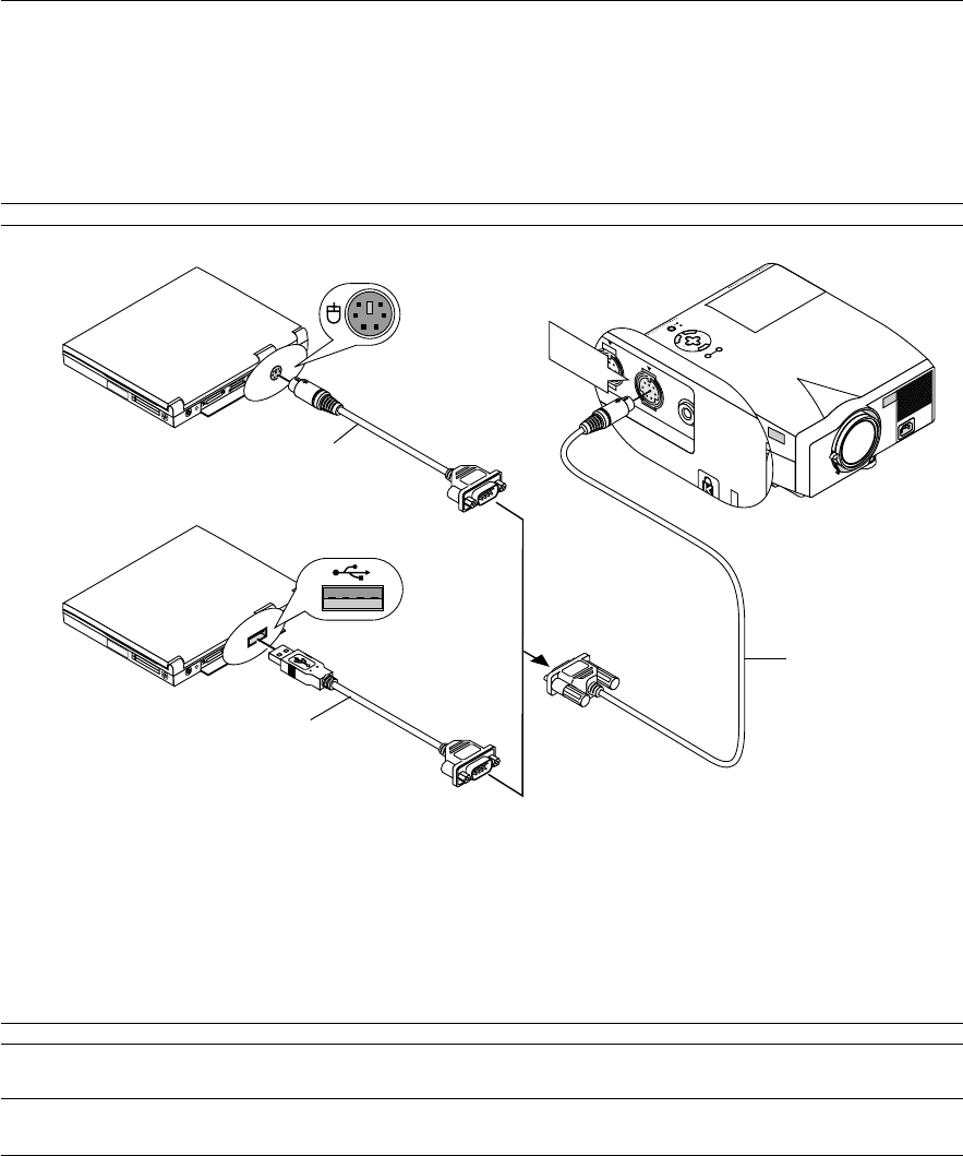
The built-in remote mouse receiver enables you to operate your computer’s mouse functions from the remote control. It is a great convenience for
clicking through your computer-generated presentations.
To connect the mouse output port:
1. Turn off your computer.
2.For PCs: Remove your current mouse and connect the supplied serial cable from the mouse output to your PC’s mouse port. (Use the 6-pin
adapter for connecting to a PS/2 computer or the supplied USB adapter.)
For Macintosh: Attach the supplied mouse adapter for USB to the mouse output port’s serial cable and connect the projector to your USB port of
a Macintosh computer.
3. When the built-in remote mouse receiver is available, it will disable your regular mouse, disconnect the serial cable and restart your computer.
NOTE: The mouse adapter for USB is not compatible with the USB terminal on the projector.
When connecting using the USB terminal
For PC, the mouse receiver can only be used with a Windows 98/2000/Me/XP operating system.
NOTE:
• Wait at least 5 seconds after disconnecting the mouse receiver before reconnecting it and vice versa. The computer may not identify the mouse receiver if it is
repeatedly connected and disconnected in rapid intervals.
Connecting Your Computer to the Mouse Output Port
Using Remote Mouse Function
The built-in remote mouse receiver enables you to operate your computer’s mouse functions from the remote control (Computer mode). It is a great
convenience for clicking through your computer-generated presentations. To return to the Projector mode, press the PJ button (lit red).
Connecting your computer to the mouse output port
If you wish to use the remote mouse function, connect the mouse output port and computer. The mouse output port can be connected directly to the
computer using the USB terminal. To connect it to the computer using the mouse (PS/2) terminal, do so using the PS/2 adapter.
NOTE: Depending on the type of connection or OS installed on your computer, you may have to restart your computer or change your computer settings.
Mouse adapter
(For IBM PS/2)
(supplied)
Mouse adapter (USB)
(supplied)
E – 21
External monitor
M
E
N
U
E
N
T
E
R
C
A
N
C
E
L
S
E
L
E
C
T
P
O
W
E
R
S
T
A
T
U
S
O
N
/
S
T
A
N
D
B
Y
S
O
U
R
C
E
A
U
T
O
A
D
J
U
S
T
A
C
IN
S
-
V
I
D
E
O
V
I
D
E
O
A
U
D
I
O
R
G
B
I
N
P
U
T
2
A
U
D
I
O
R
G
B
I
N
P
U
T
1
L
/
M
O
N
O
R
A
U
D
I
O
R
G
B
M
O
N
I
T
O
R
O
U
T
P
U
T
U
S
B
P
C
-
C
A
R
D
C
C
O
N
T
R
O
L
M
O
U
S
E
O
U
T
R
E
M
O
C
O
N
T
R
I
N
P
U
S
-V
ID
E
O
V
ID
E
O
A
U
D
IO
R
G
B
IN
P
U
T
2
AUDIORGB INPUT 1
L
/
M
O
N
O
R
AUDIO
RGB MONITOR
OUTPUT
RGB INPUT
RGB OUTPUT
AUDIO IN
AUDIO OUT
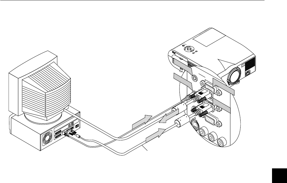
Connecting an External Monitor
You can connect a separate, external monitor to your MT1056 to simultaneously view on a monitor the image you’re projecting. To do so:
1. Turn off the power to your projector, monitor and computer.
2. Use a 15-pin cable to connect your monitor to the RGB Monitor Output (Mini D-Sub 15 pin) connector on your projector.
3. Turn on the projector, monitor and the computer.
RGB Signal cable (suppried)
E – 22
Connecting Your DVD Player
M
E
N
U
E
N
T
E
R
C
A
N
C
E
L
S
E
L
E
C
T
P
O
W
E
R
S
T
A
T
U
S
O
N
/
S
T
A
N
D
B
Y
S
O
U
R
C
E
A
U
T
O
A
D
J
U
S
T
A
C
I
N
S
-
V
I
D
E
O
V
I
D
E
O
A
U
D
I
O
R
G
B
I
N
P
U
T
2
A
U
D
I
O
R
G
B
I
N
P
U
T
1
L
/
M
O
N
O
R
A
U
D
I
O
R
G
B
M
O
N
I
T
O
R
O
U
T
P
U
T
U
S
B
P
C
-
C
A
R
D
C
C
O
N
T
R
O
L
M
O
U
S
E
O
U
T
R
E
M
O
C
O
N
T
R
I
N
P
U
S-VIDEO
VIDEO
AUDIORGB INPUT 2
A
U
D
IO
R
G
B
IN
P
U
T
1
L
/
MONO
R
A
U
D
IO
R
G
B
M
O
N
IT
O
R
O
U
T
P
U
T
RGB INPUT
R L
Y Cb Cr
R L
AUDIO
Component
AUDIO
You can connect your projector to a DVD player with component outputs or Video output. To do so, simply:
1. Turn off the power to your projector and DVD player.
2. If your DVD player has the component video (Y/Cb/Cr) output, use a commercially available component video cable (RCA3) and the optional
15-pin-to-RCA (female)3 cable to connect your DVD player to the RGB INPUT connector on the projector.
For a DVD player without component video (Y/Cb/Cr) outputs, use common RCA cables (not provided) to connect a composite VIDEO output of
the DVD player to the Video Input of the projector.
3. Turn on the projector and DVD player.
NOTE: Refer to your DVD player’s owner’s manual for more information about your DVD player’s video output requirements,
Optional 15-pin-to-RCA (female)3
cable (ADP-CV1)
Audio cable
(not supplied)
DVD player
White
Red
Y
Cb
Cr
White
Red
Audio Equipment
Component video cable
RCA3 (not supplied)
E – 23
M
E
N
U
E
N
T
E
R
C
A
N
C
E
L
S
E
L
E
C
T
P
O
W
E
R
S
T
A
T
U
S
O
N
/
S
T
A
N
D
B
Y
S
O
U
R
C
E
A
U
T
O
A
D
J
U
S
T
A
C
I
N
S
-
V
I
D
E
O
V
I
D
E
O
A
U
D
I
O
R
G
B
I
N
P
U
T
2
A
U
D
I
O
R
G
B
I
N
P
U
T
1
L
/
M
O
N
O
R
A
U
D
I
O
R
G
B
M
O
N
I
T
O
R
O
U
T
P
U
T
U
S
B
P
C
-C
A
R
D
C
C
O
N
T
R
O
L
M
O
U
S
E
O
U
T
R
E
M
O
C
O
N
T
R
I
N
P
U
S-VIDEO
VIDEO
AUDIORGB INPUT 2
A
UD
IO
R
G
B IN
PU
T 1
L
/
MONO
R
AU
D
IO
RG
B M
O
N
ITO
R
O
U
TPU
T
VIDEO
S-VIDEO
R L
R L
VIDEO
VCR/ Laser disc player
S-video cable (not supplied)
Audio equipment
Audio cable (not supplied)
Document camera
Video cable (not supplied)
Connecting Your VCR or Laser Disc Player
Use common RCA cables (not provided) to connect your VCR, laser disc player or document camera to your projector.
To make these connections, simply:
1. Turn off the power to the projector and VCR, laser disc player or document camera.
2. Connect one end of your RCA cable to the video output connector on the back of your VCR or laser disc player, connect the other end to the Video
input on your projector. Use an audio cable (not supplied) to connect the audio from your VCR or laser disc player to your audio equipment (if your
VCR or laser disc player has this capability). Be careful to keep your right and left channel connections correct for stereo sound.
3. Turn on the projector and the VCR or laser disc player.
NOTE: Refer to your VCR or laser disc player owner’s manual for more information about your equipment’s video output requirements.
E – 24
About Startup screen
(Menu Language Select screen)
When you first turn on the projector, you will get the Startup screen.
This screen gives you the opportunity to select one of the seven menu
languages: English, German, French, Itilan, Spanish, Swedish and
Japanese.
To select a menu language, follow these steps:
1.Use the Select ▲ or ▼ button to select one of the seven languages
for the menu.
2.Press the Enter button to execute the selection.
3.The Basic/Custom menu will be displayed in the language you
have selected.
To close the menu, press the Cancel button.
After this has been done, you can proceed to the advanced menu op-
eration.
If you want, you can select the menu language later. See “Language”
on page E-35.
E – 25
3. OPERATION
This section describes how to select a computer or video source, how
to adjust the picture, and how to customize the menu or projector set-
tings.
General Controls
Before you turn on your projector, ensure that the computer or video
source is turned on and that your lens cap is removed.
1.Turn on the Projector
Plug the supplied power cable in the wall outlet. The projector
will go into its standby mode and the power indicator will glow
orange.
Only after you press the “On” button on the remote control (“ON/
STAND BY” button on the projector cabinet) will the power indi-
cator turn to green and the projector become ready to use.
NOTE: To turn the projector on by plugging in the power cable, use the
menu and enable the “Auto Start” feature. (See page E-37.)
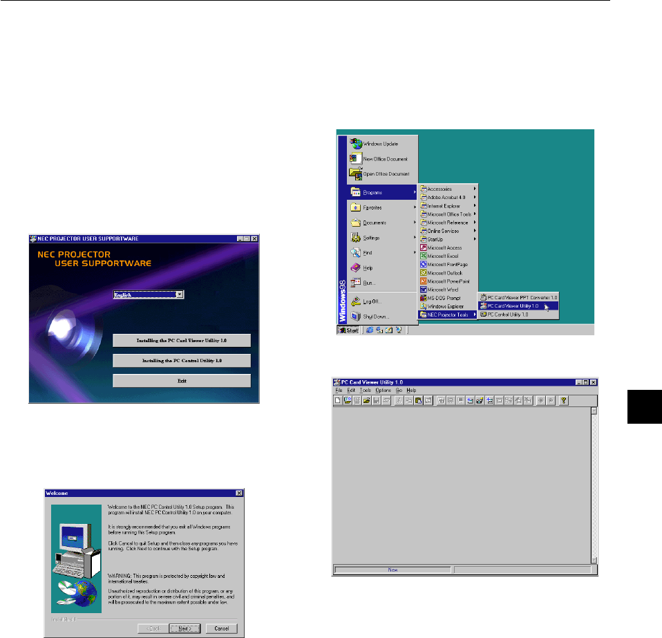
2.Select the Computer, Video Source or PC Card Viewer
Press a source button on the remote control or the projector cabi-
net to select “Video” (VCR, document camera, or laser disc
player), “S-Video”, “RGB 1 or 2” (computer or DVD with com-
ponent output) or “PC Card Viewer” to display the image.
Or press the “Menu” button on the remote control or the cabinet
and use the menu to select your video source: “Video”, “S-Video”,
“RGB1 or 2”, or “PC Card Viewer”.
3.Adjust the Image Size and the Focus
Use the Zoom lever to adjust the image size, then use the Focus
ring to obtain the best focus.
Use the “Magnify” button (+) or (-) on the remote control to make
the image larger up to 400%.
4.Turning off the Projector
First press the “off” button on the remote control (“ON/STAND
BY” button on the projector cabinet) for a minimum of two sec-
onds. The power indicator will glow orange. Then, unplug the
power cable. The power indicator will go out.
IMPORTANT:
•The projector should be unplugged if it will not to be used for an
extended period.
•To turn off the image and sound briefly (five minutes or less), use
the “Picture Mute” button instead of turning the projector off and on.
•The projector will display a black, blue image or logo if no input sig-
nal is present.
•Do not turn the projector off and then immediately back on. The
projector needs to cool for a minute before it can be restarted.
After the projector turns off, the cooling fans keep operating for a full
minute.
Do not disconnect the power cable during this time.
Using the Menus
NOTE: The on-screen menu may not be displayed correctly while interlaced
motion video image is projected.
1.Press the “Menu” button on the remote control or projector cabi-
net to display the Main Menu.
NOTE: When using a USB mouse, click the mouse button to display the
main menu. For other operations, do the same way as you use your PC
mouse.
2.Press the ▲▼ buttons on the remote control or the projector cabi-
net to highlight the menu for the item you want to adjust or set.
3.Press the
button or the “Enter” button on the projector cabinet
or the remote control to select a submenu or item.
4.Adjust the level or turn the selected item on or off by using “Se-
lect”
or
buttons on the cabinet or the remote control. The on-
screen slide bar will show you the amount of increase or decrease.
5.Changes are stored until you adjust it again.
ENTER.........Stores the setting or adjustments.
CANCEL..........
Return to the previous screen without storing settings or ad-
justments.
NOTE: You can close the main and sub menus simultaneously by pressing
the PJ button to cancel the Projector mode.
6.Repeat steps 2-5 to adjust an additional item, or press “Cancel”
on the projector cabinet or the remote control to quit the menu
display.
Using a USB Mouse
Using a USB mouse gives you a smooth operation. A commercially
available USB mouse is required.
NOTE: There may be some brands of USB mouse that the projector does not
support.
Operate the Menus using the USB mouse:
Mouse Cursor:
When connecting a USB mouse to the projector, you get a mouse
cursor on the screen.
Unless you use your USB mouse within 10 seconds, the mouse
cursor disappears.
Menu Display:
Clicking with a mouse button displays the main menu.
Clicking
displays the pull-down menu.
To close the menu, click anywhere in the background.
Adjusting and Setting Display:
You can select a menu item and click with a mouse button to make
adjustments and setting.
Examples:
Click (or press and hold) the mouse button
or
to adjust the
brightness.
Or click and drag the mouse button on the slide bar horizontally to
adjust it.
To save the adjustments, click
. The display is closed.
If you click anywhere in the background while displaying adjust-
ment and setting menu or dialog box, you will get the main menu at
the clicking point.
NOTE: The MOUSE OUTPUT port on the projector is not compatible with the
USB mouse.
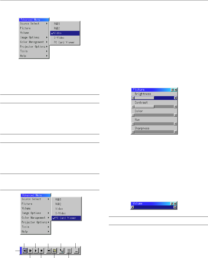
E – 26
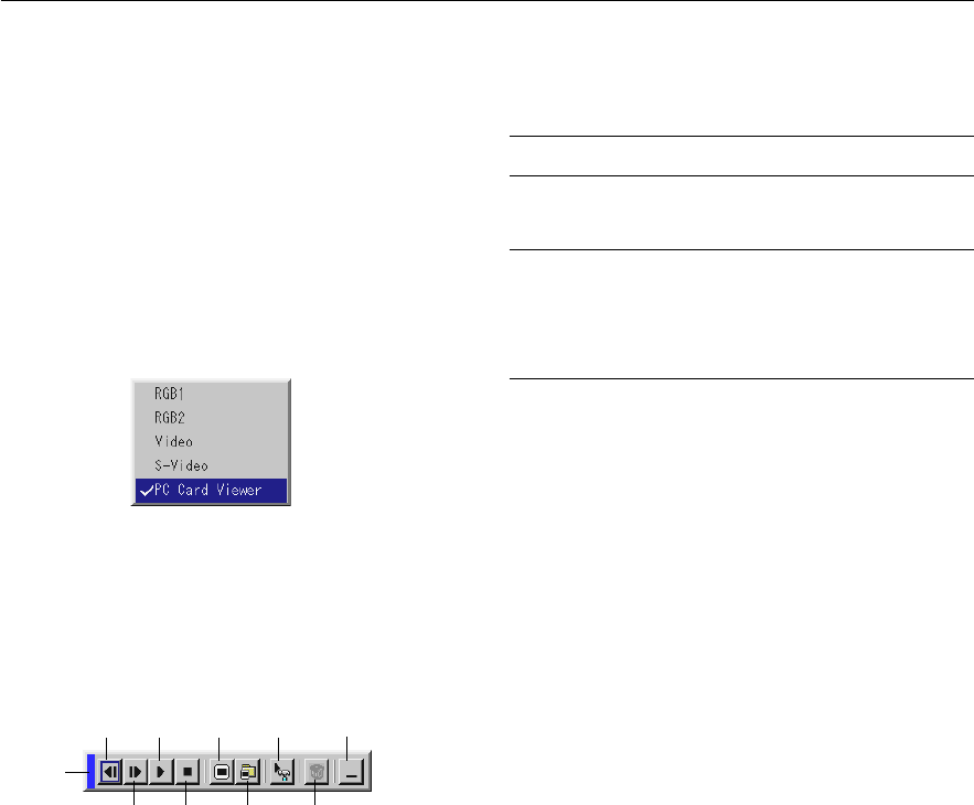
Source display
SOURCEAUTO ADJUST
Each time the Source button is pressed, the input source will change
as follows:
→ RGB1 → RGB2 → Video → S-Video → PC Card Viewer
If no input signal is present, the input will be skipped.
Press the Auto Adjust button to fine-tune the computer image or to
remove any vertical banding that might appear and to reduce video
noise, dot interference or cross talk (this is evident when part of your
image appears to be shimmering). This function adjusts the clock fre-
quencies that eliminate the horizontal banding in the image. This func-
tion also adjusts the clock phase to reduce video noise, dot interfer-
ence or cross talk. (This is evident when part of your image appears to
be shimmering.)
This adjustment may be necessary when you connect your computer
for the first time.
NOTE: The Auto Adjust function does not work for component signal.
Basic Operation
Selecting the computer or video source:
Adjust the Image Using Auto Adjust
The Auto Adjust function automatically optimizes the image in RGB
mode.
AUTO ADJUST
[Poor picture]
[Normal picture]
VIDEOS-VIDEORGB1RGB2
PC CARD
M
E
N
U
OFF
VIDEO
AUTO ADJ.
S-VIDEORGB1RGB2
LASER
ON
SC
POWER
E – 27
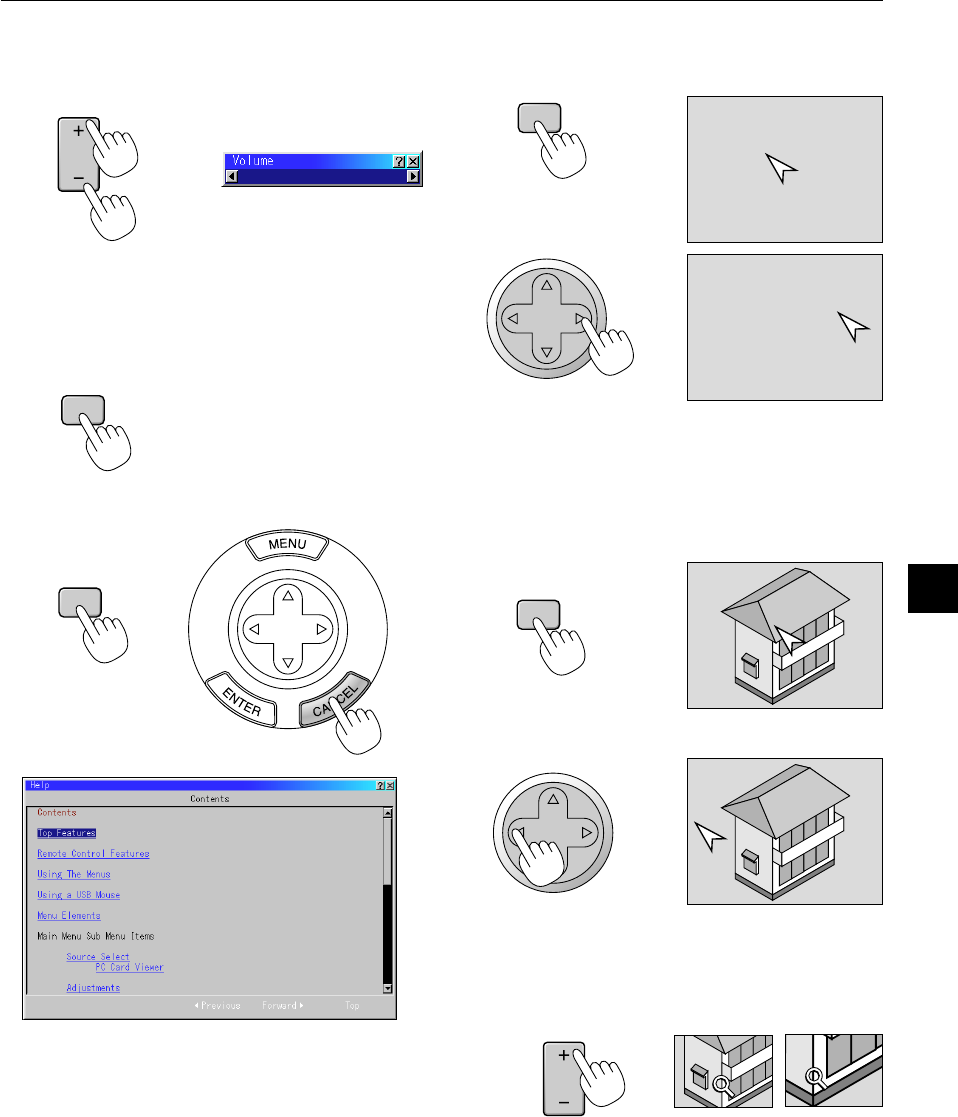
Volume control:
Sound level from the speaker on the projector can be adjusted.
increase volume
VOLUME
Volume bar
decrease volume
Turning off picture and sound:
Press the Picture Mute button to turn off the image and sound for a
short period of time. Press again to restore the image and sound.
PIC
-
MUTE
Getting Help about how to operate the projector:
You get the contents about Help.
Display Help
Exit Help
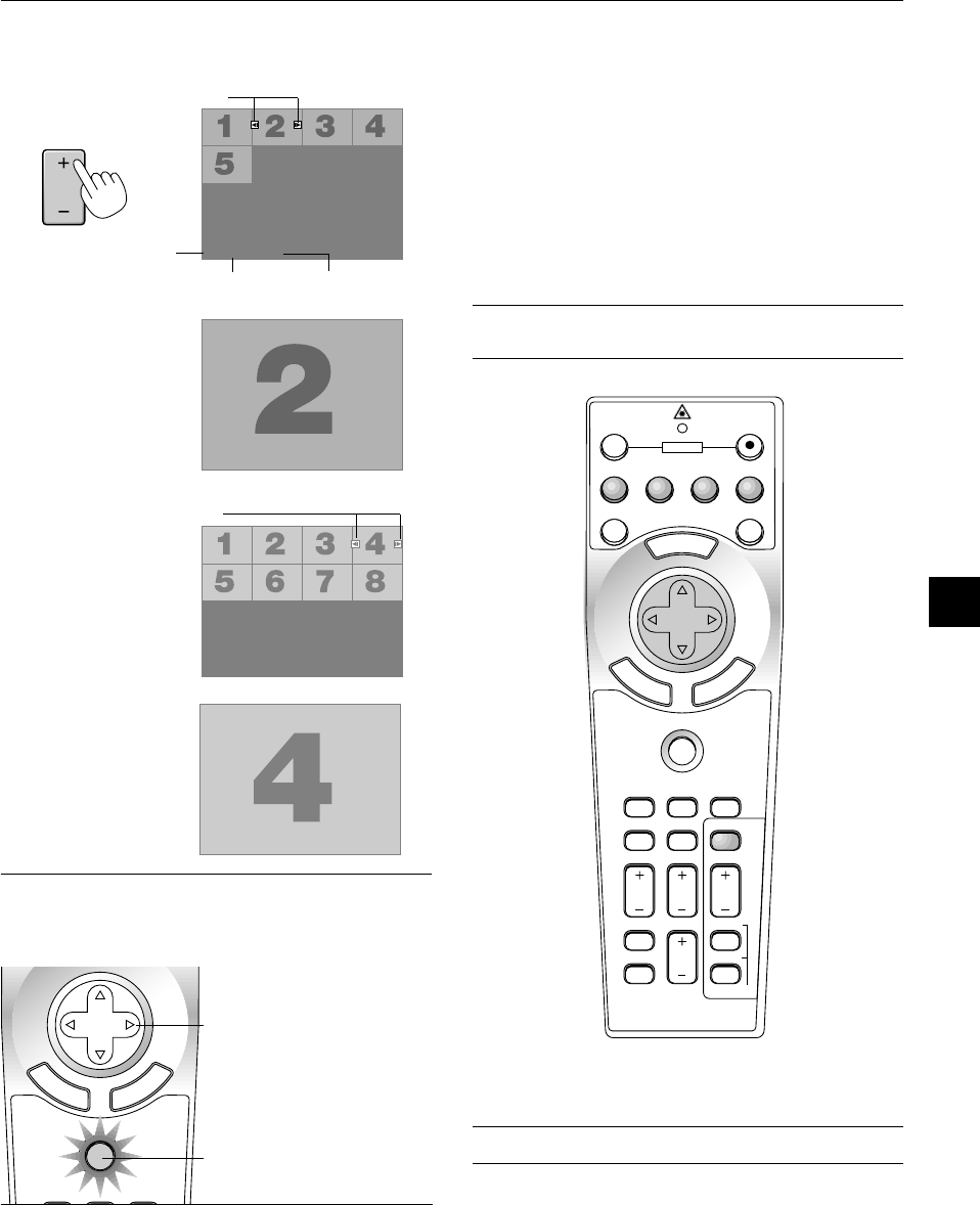
Using Pointer
You can use one of eight pointers to draw your audience’s attention to
the portion of a projected image you want.
Press the Pointer button to
display the pointer.
Use the Select button to
move the pointer.
Enlarging and Moving a Picture
You can enlarge the area you want up to 400 percent.
To do so:
1.Press the Pointer button to display the pointer.
2.Move the pointer to the area you want to enlarge.
3.Enlarge the selected area.
When the Magnify (+) button is pressed, the pointer is changed to
a magnifying glass. To move the magnifying glass, use the Select
button.
MAGNIFY
HELP
POINTER
POINTER
SELECT
SELECT
SELECT
E – 28
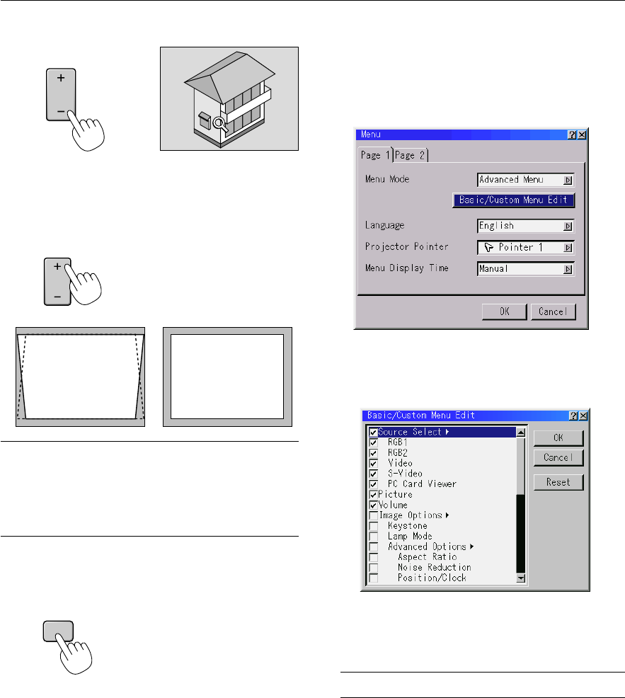
Customizing Basic/Custom Menu
The Basic/Custom menu can be customized to meet your requirements.
Selecting a menu item from the “Basic/Custom Menu Edit” list, allows
you to custom tailor the menu items to your needs.
1.Select “Basic/Custom Menu Edit” to display the “Basic/Custom
Menu Edit” screen.
2.Use the ▲ or ▼ button to highlight your selection and press the
Enter button to place a check mark next to an option. This action
enables that feature.
Press the Enter button again to clear the check box.
If you select an item with a solid triangle
and press the Enter
button on the remote control or the projector cabinet, you can
enable all the items within that submenu.
Also you can turn on an item within the submenu without placing
a check mark on the main menu item.
NOTE: Up to 12 main menu items (within Basic/Custom Menu Edit, not
including submenu items) can be selected.
4.Return the image to the original size.
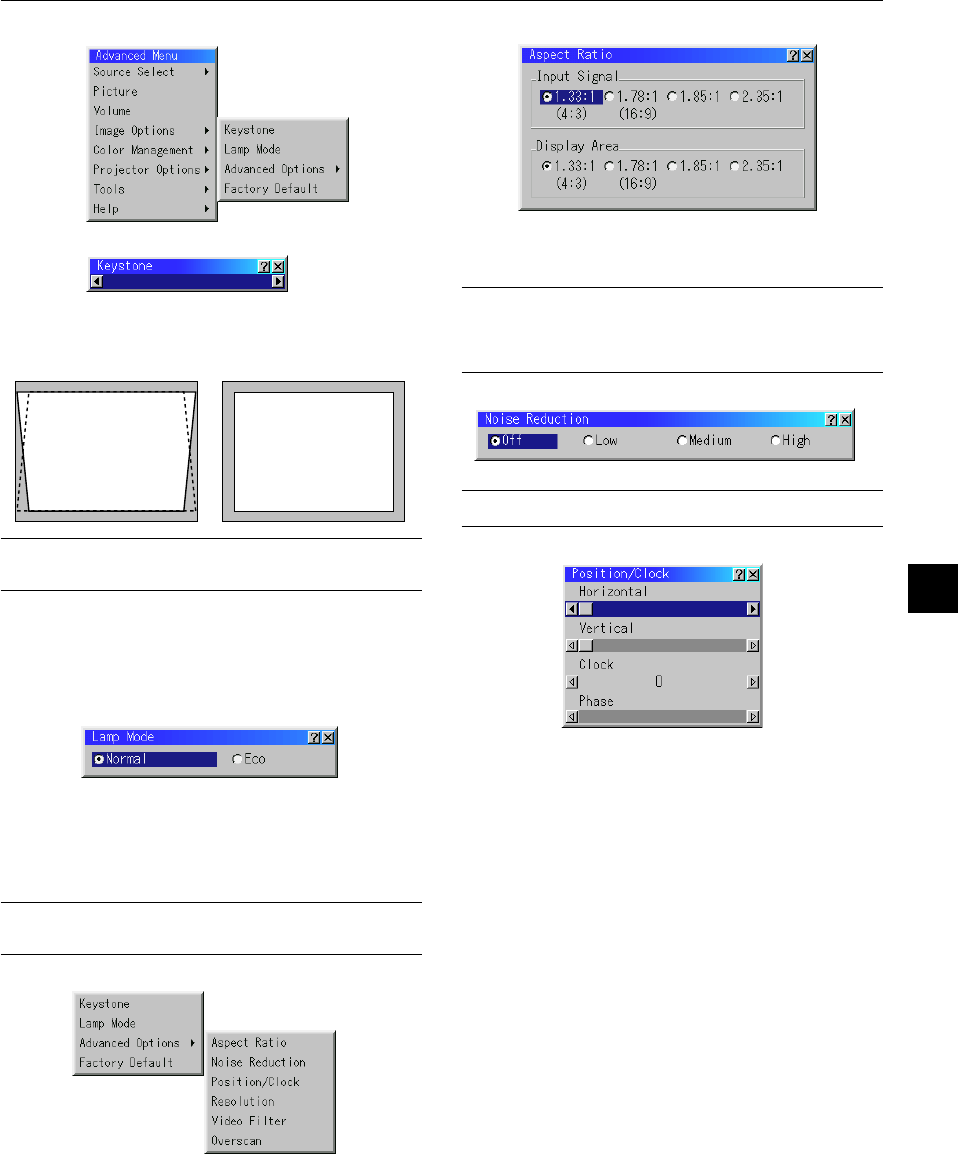
Correcting Keystone distortion
Press (+) or (-) to correct keystone (trapezoidal) distortion to make the
top or bottom of the screen longer or shorter so that the projected
image is rectangular.
KEYSTONE
NOTE: The maximum keystone angle that can be corrected is 40 degrees up-
ward and 20 degrees downward with the projector placed horizontally on the
ground plane.
Depending on the type of graphics being used, the picture may get blurred or
keystone correction may not be possible when excessive keystone correction
is used.
The idea is, the closer you are to native resolution, the better image you will
see.
Freezing a picture
Press the Freeze button to freeze a picture. Press again to resume
motion.
Keystone distortionNormal
MAGNIFY
FREEZE
E – 29
3.In order for the changes to take effect, use the
or
button on
the remote control or the projector cabinet to highlight “OK”,
then press the Enter button. To cancel the changes, use the ▲ or
▼ buttons to highlight “Cancel” and press the “Enter” button.
To return to the factory default, select “Reset” then press the “En-
ter” button.
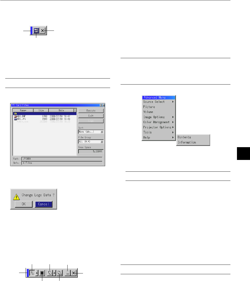
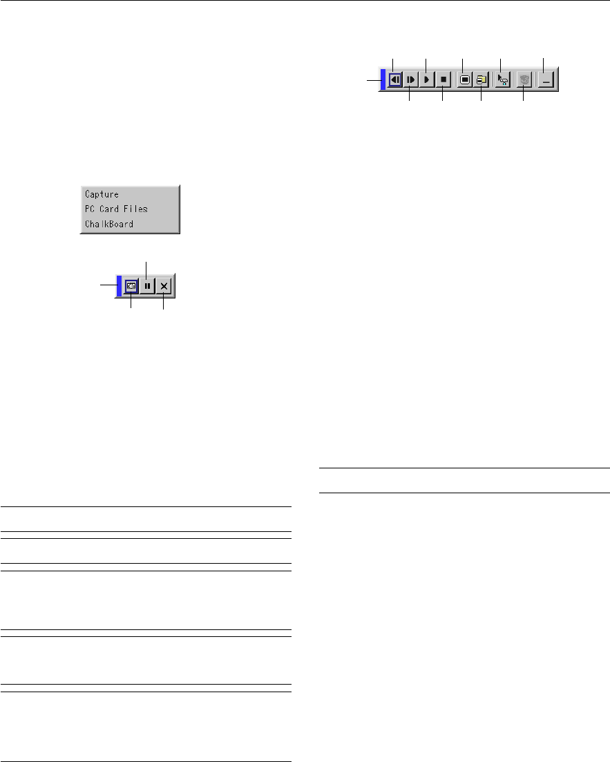
The default Basic/Custom Menu items are:
Source Select (RGB1/2, Video, S-Video and PC Card Viewer), Pic-
ture, Volume, Image Options (Keystone and Lamp Mode), Projec-
tor Options (Menu and Setup), Tools (Capture, PC Card Files and
ChalkBoard) and Help (Contents and Information)
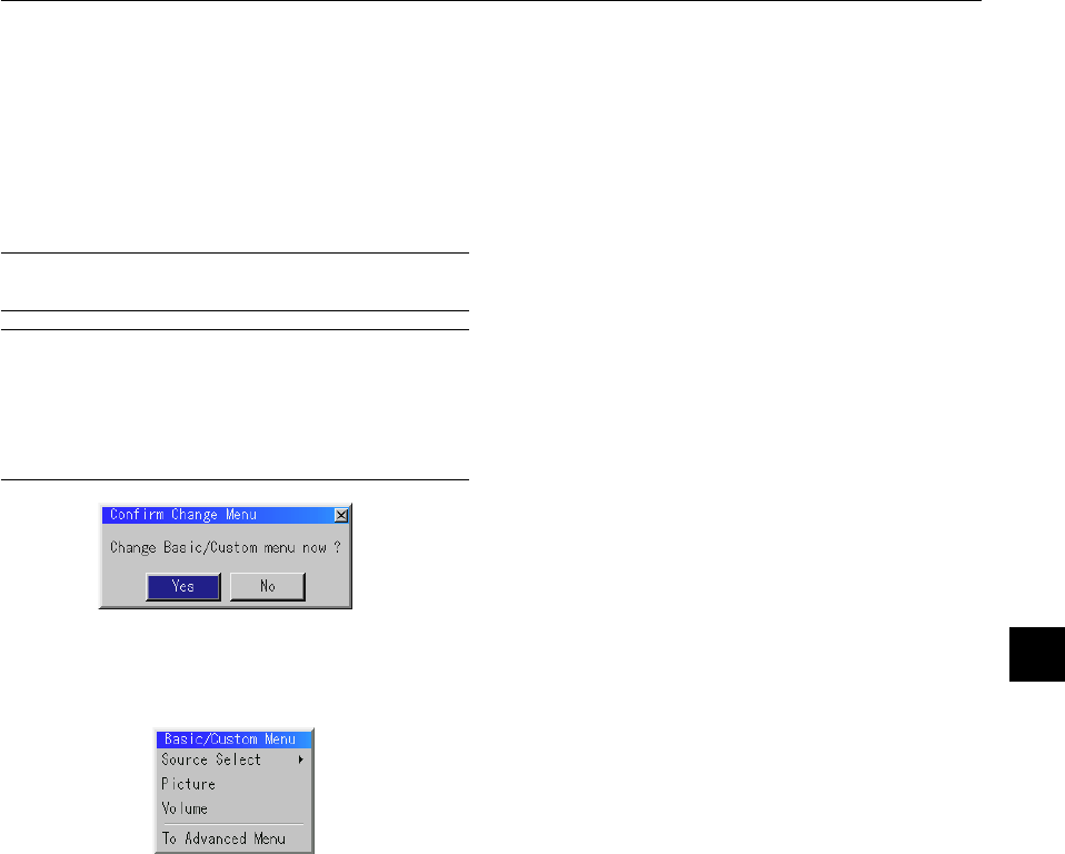
NOTE: Once you have selected OK on the Basic/Custom Menu Edit screen, you
cannot cancel the changes on the Menu screen. However, you can re-edit the
menu items over again as described in the steps above.
NOTE: If the “Advanced Menu” item has been selected on the Menu mode, you
get the “Confirmation Change Menu” upon completion of “Basic/Custom Menu”
editing. In this case, selecting “Yes” then “Enter” will close all the menus and
apply the changes from the Advanced menu to the Basic/Custom Menu. If you
select “No” then “Enter” functions, then all menu items will return to the Ad-
vanced menu, but your changes will still be available within the “Basic/Custom
Menu” selection. To display the previously tailored Basic/Custom Menu, select
“Basic/Custom Menu” from the “Menu Mode”.
An item “To Advanced Menu” will be added to the bottom of the Basic/
Custom Menu.
Selecting this item and pressing the “Enter” button will display the “Ad-
Libble nimmt den Missbrauch seiner Dienste sehr ernst. Wir setzen uns dafür ein, derartige Missbrauchsfälle gemäß den Gesetzen Ihres Heimatlandes zu behandeln. Wenn Sie eine Meldung übermitteln, überprüfen wir Ihre Informationen und ergreifen entsprechende Maßnahmen. Wir melden uns nur dann wieder bei Ihnen, wenn wir weitere Einzelheiten wissen müssen oder weitere Informationen für Sie haben.
Art des Missbrauchs:
Forenregeln
Um zu sinnvolle Fragen zu kommen halten Sie sich bitte an folgende Spielregeln:
Lesen Sie zuerst die Anleitung;
Schauen Sie nach, ob die Frage bereits gestellt wurde;
Stellen Sie die Frage so deutlich wie nur einigermaßen möglich;
Erwähnen Sie was Sie bereits versucht haben um das Problem zu lösen;
Ist Ihr Problem von einem Besucher gelöst dann lassen Sie ihn / sie wissen in diesem Forum;
Falls Sie reagieren möchten, so verwenden Sie bitte das Antworten- Formular;
Da ihre Frage für alle Besucher sichtbar ist, sollten Sie lieber keine persönliche Daten erwähnen.
Neu registrieren
Registrieren auf E - Mails für Nec MT1056 wenn:
neue Frage gestellt werden
neue Handbücher vorhanden sind
Sie erhalten eine E-Mail, um sich für eine oder beide Optionen anzumelden.
Das Handbuch wird per E-Mail gesendet. Überprüfen Sie ihre E-Mail.
Wenn Sie innerhalb von 15 Minuten keine E-Mail mit dem Handbuch erhalten haben, kann es sein, dass Sie eine falsche E-Mail-Adresse eingegeben haben oder dass Ihr ISP eine maximale Größe eingestellt hat, um E-Mails zu erhalten, die kleiner als die Größe des Handbuchs sind.
Ihre Frage wurde zu diesem Forum hinzugefügt
Möchten Sie eine E-Mail erhalten, wenn neue Antworten und Fragen veröffentlicht werden? Geben Sie bitte Ihre Email-Adresse ein.