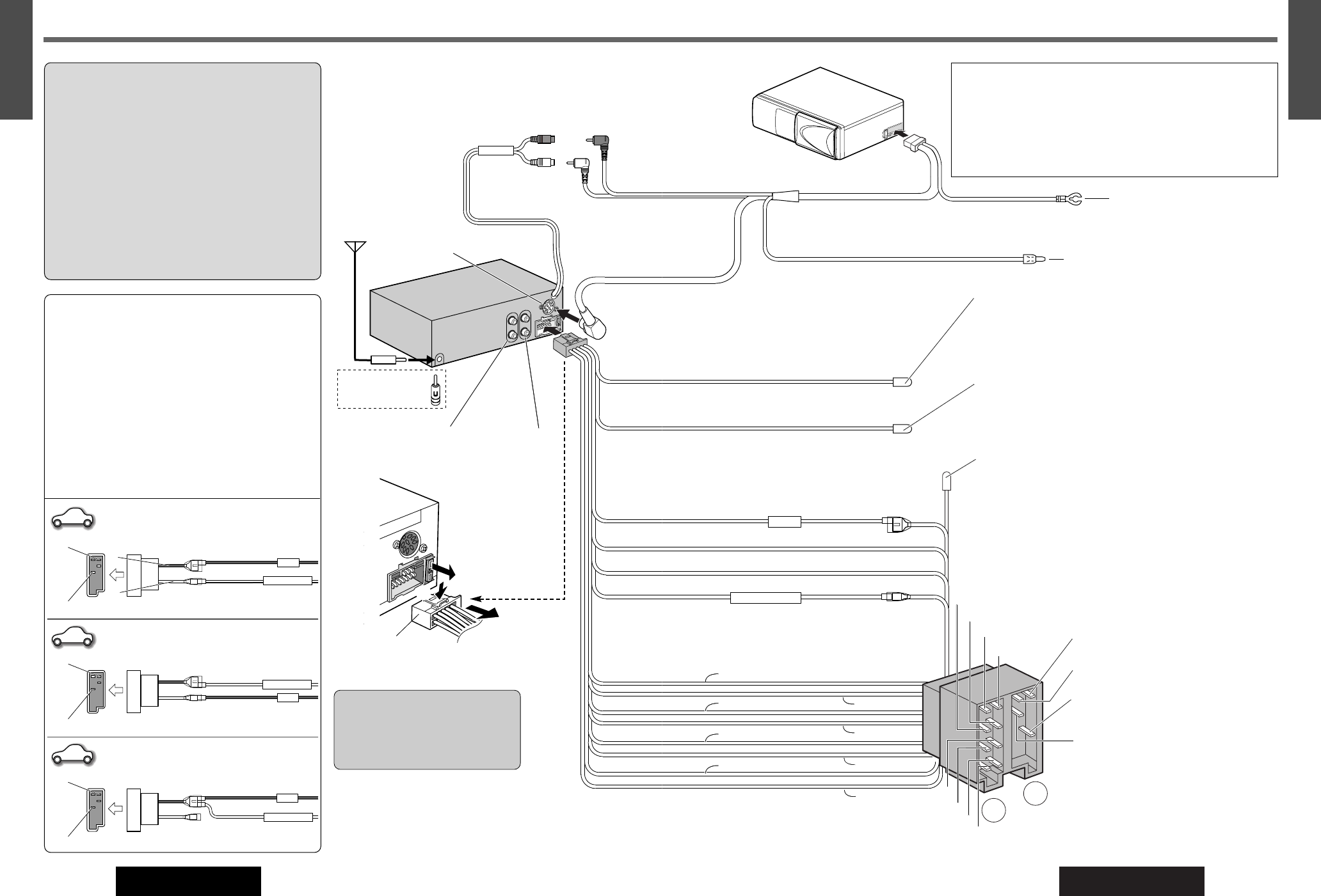
¡This unit can be connected to an optional CD changer (CX-
DP880N, CX-DP9061/DP9060EN, CX-DP88N, CX-DP801/
DP803EN or CX-DP601EN) and optional extension cord.
¡For details consult your nearest authorized Panasonic Dealer.
¡For connection to a CD changer, refer to the operating instruc-
tions of the CD changer (CX-DP880N, CX-DP9061/DP9060EN,
CX-DP88N, CX-DP801/DP803EN or CX-DP601EN).
A5*: This lead can be used as either Amp
.
Relay Control Power Lead or Motor Antenna Relay Control Lead, or both at the
same time. However, the current capacity of this lead is 500 mA.
A8 (Black)
A7 (Red)
A4 (Yellow)
A5 (Blue w/white stripe)
B8 (Green w/black stripe)
B7 (Green)
B6 (White w/black stripe)
B5 (White )
B4 (Gray w/black stripe)
B3 (Gray)
B2 (Violet w/black stripe)
B1 (Violet )
A5* (Blue w/white stripe)
A5* : Motor Antenna Relay Control Lead
(Blue w/white stripe)
To Motor Antenna (Max. 500 mA)
*
. This lead
is not intended for use with a switch actuated
power antenna.
Note: The power antenna extends automati-
cally when the power of this unit is turned on.
A7 : Power Lead (ACC or IGN) (Red)
To ACC power, +12 V DC.
A8 : Ground Lead (Black)
To a clean, bare metallic part of the car chassis.
A4 : Battery Lead (Yellow)
To the car battery, continuous +12 V DC.
B8 : Rear Left –
B7 : Rear Left +
B6 : Front Left –
B5 : Front Left +
B4 : Front Right –
B3 : Front Right +
B2 : Rear Right –
B1 : Rear Right +
Speakers
C1 : External Mute Lead (Orange)
Telephone Mute: Connect to the car telephone mute lead.
Note: The telephone mute lead is only for connection to the radio
mute lead. Output other than telephone will not be muted
Navi Mute: To the Navi Mute lead of the Panasonic car navigation
system.
Battery Lead (Yellow)
To the car battery, continuous +12 V DC
Ground Lead (Black)
To a clean, bare metallic part
of the car chassis
C3 : External Remote Control Lead
(Brown w/black stripe)
When using a non-Panasonic external remote control, refer
to the manufacture for their product before connecting.
CD Changer
CX-DP880N (Option)
Extension Cord
(DIN/BATT/RCA/GND)
(Supplied for an optional CD Changer)
DIN Cord
B1
B2
B4
B3
B5
B6
B7
B8
Electrical Connections
Cautions:
¡Check the connectors provided on your car (see
precaution below) before connecting the system.
¡This unit is designed for use in a car having a 12-
volt negative ground battery system.
¡To prevent damage to the unit, be sure to follow
the connection diagram.
¡Strip about 5 mm of the lead ends for connection
(only non-ISO connector cords).
¡Do not insert the power connector into the unit
until the wiring is completed.
¡Be sure to insulate any exposed wires to prevent
short circuiting with the car chassis. Bundle all
cables, and prevent cable terminals from touching
any metal parts.
Precautions (ISO Connector)
¡The pin arrangement of the power connector
conforms to ISO standard.
¡The pin arrangement of ISO connectors in some
cars may differ from the ISO standard.
¡Please check that the pin arrangement of the
connector in your car conforms to ISO standard.
¡For car types A and B, change the wiring of the
red and yellow leads as shown at below.
¡After connection, insulate the portions marked
(C) with insulating tape.
Note: For cars other than types A and B, please
consult your local car shop.