657865
23
Zoom out
Zoom in
Vorherige Seite
1/32
Nächste Seite
Instruction Manual
23
E04054
4.2 Transducer Installation
4.2.1 Running the Cable
It is easiest to run the transducer cable if the mast is stepped. If
this is not possible, all necessary precautions should be taken -
always use a bosuns chair and ensure all tools are securely
attached when working aloft.
Apply the self-adhesive template supplied to the masthead,
pointing fore-aft. Drill the fixing and cable exit holes as
marked - the masthead bracket incorporates a cable clamp to
secure the transducer cable and provide strain relief (Fig 4.7) -
NOTE The cable can be fed through the side of the mast if this is more
convenient.
It is recommended that a grommet is used to avoid damage the
cable where it passes through the mast. Allow at least 75mm
(3.0”) of cable at the masthead for the transducer connection.
For boats with an aluminium mast, a channel is normally pro-
vided inside the mast Section for running electrical cables.
This will usually have a tag line, or “mouse” - a length of line
running the length of the mast to assist in pulling through
cables. If not, the cable will need to be fed down and drawn
out the bottom by hand.
For boats with a wooden mast, the cable can be run down the
outside of the mast, held in place with galvanised cable clips.
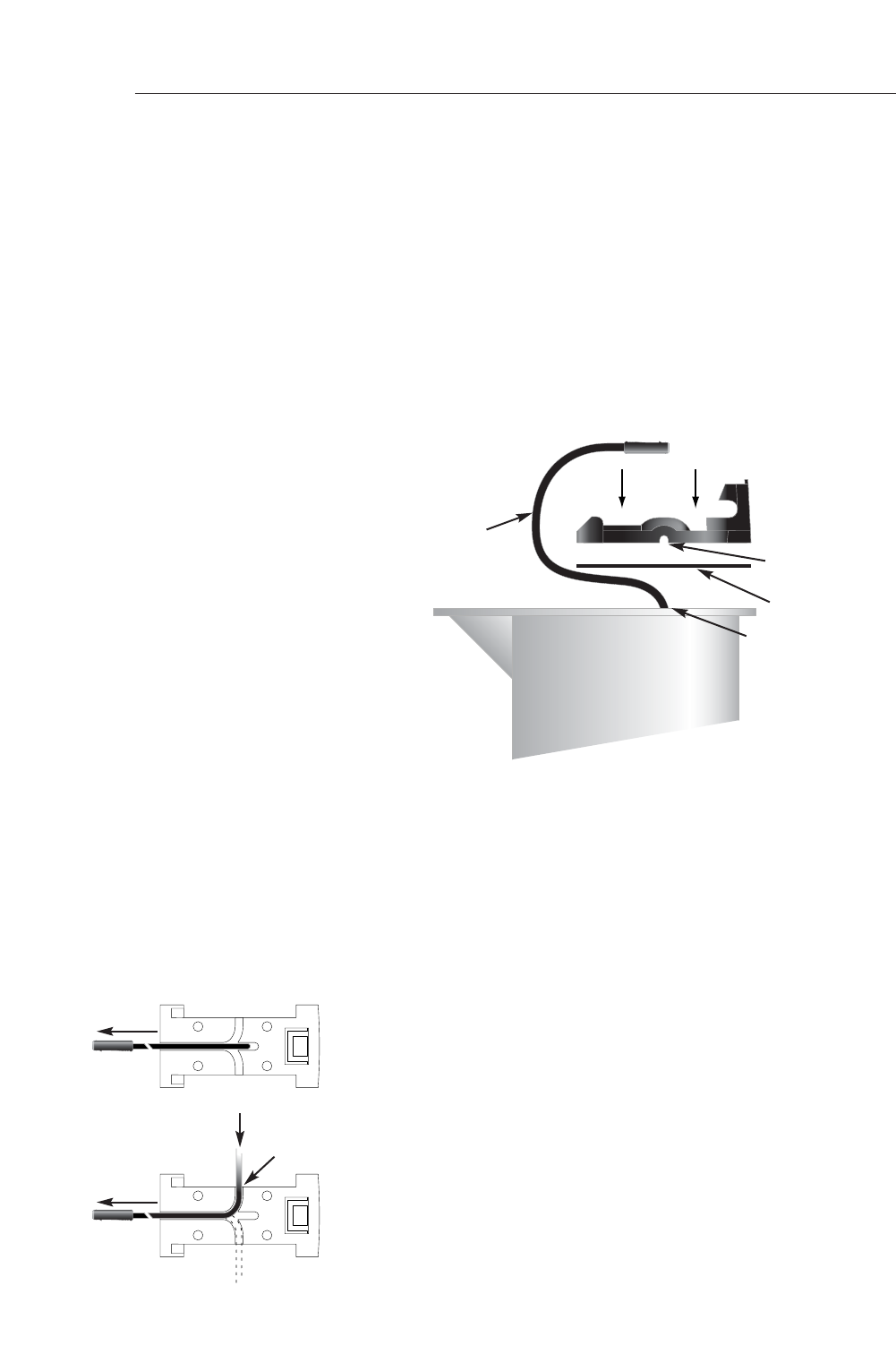
4.2.2 Fitting the Masthead Bracket
Route the transducer cable in the strain relief channels in the
bracket and out the back. If the cable exits through the side of
the mast, route the cable in one of the blanked off side chan-
nels and out the back (Fig 4.8). Use a sharp knife or scalpel to
remove the blanking piece and open up the channel.
Cable exit point
MASTHEAD
Cable clamp
channels
Allow 75mm (3.0”) of
cable at the masthead
Fig 4.7 - Drilling Exit Hole for Transducer Cable
Fig 4.8 - Cable Channel
Exit Points
Mast Top Cable Exit
Mast Side Cable Exit
Gasket
Cut out
blanking
piece
23

Brauchen Sie Hilfe? Stellen Sie Ihre Frage.

Forenregeln
1

Forum

simrad-is12

Suche zurücksetzen

  • Hallo. An der Platine im Gehäuse meines Simrad is12:tw sind die Kabel an den Lötstellen abgegangen. Wer kann mir die Positionen der einzelnen Farben angeben. Eingereicht am 21-1-2021 10:43

    Antworten Frage melden
  • Was brauche ich für simrad an kabel und verbindungen für s 27 ? Eingereicht am 26-1-2018 11:28

    Antworten Frage melden

Missbrauch melden von Frage und/oder Antwort

Libble nimmt den Missbrauch seiner Dienste sehr ernst. Wir setzen uns dafür ein, derartige Missbrauchsfälle gemäß den Gesetzen Ihres Heimatlandes zu behandeln. Wenn Sie eine Meldung übermitteln, überprüfen wir Ihre Informationen und ergreifen entsprechende Maßnahmen. Wir melden uns nur dann wieder bei Ihnen, wenn wir weitere Einzelheiten wissen müssen oder weitere Informationen für Sie haben.

Art des Missbrauchs:

Zum Beispiel antisemitische Inhalte, rassistische Inhalte oder Material, das zu einer Gewalttat führen könnte.

Beispielsweise eine Kreditkartennummer, persönliche Identifikationsnummer oder unveröffentlichte Privatadresse. Beachten Sie, dass E-Mail-Adressen und der vollständige Name nicht als private Informationen angesehen werden.

Forenregeln

Um zu sinnvolle Fragen zu kommen halten Sie sich bitte an folgende Spielregeln:

Neu registrieren

Registrieren auf E - Mails für Simrad IS12 wenn:


Sie erhalten eine E-Mail, um sich für eine oder beide Optionen anzumelden.


Andere Handbücher von Simrad IS12

Simrad IS12 Bedienungsanleitung - Deutsch - 102 seiten


Das Handbuch wird per E-Mail gesendet. Überprüfen Sie ihre E-Mail.

Wenn Sie innerhalb von 15 Minuten keine E-Mail mit dem Handbuch erhalten haben, kann es sein, dass Sie eine falsche E-Mail-Adresse eingegeben haben oder dass Ihr ISP eine maximale Größe eingestellt hat, um E-Mails zu erhalten, die kleiner als die Größe des Handbuchs sind.

Ihre Frage wurde zu diesem Forum hinzugefügt

Möchten Sie eine E-Mail erhalten, wenn neue Antworten und Fragen veröffentlicht werden? Geben Sie bitte Ihre Email-Adresse ein.


Info