675520
1
Zoom out
Zoom in
Vorherige Seite
1/32
Nächste Seite
310 648 03
C
TR 642 S
TR 644 S
TR 642 S DCF
TR 644 S DCF
TR 686/ 4 DCF
TR 686/ 4b DCF
Bedienungsanleitung (Seite 2 – 26)
Mode d’emploi (page 27 – 50)
Operating Instructions (Page 51 – 74)
Istruzioni d’uso (pag. 75 – 98)
Gebruiksaanwijzing (pag. 99 – 122)
Mit Software Obelisk
programmierbar
Programmation avec
logiciel Obelisk
Time switch programming
with software Obelisk
Programmazione con
software Obelisk
Programmering met
software Obelisk
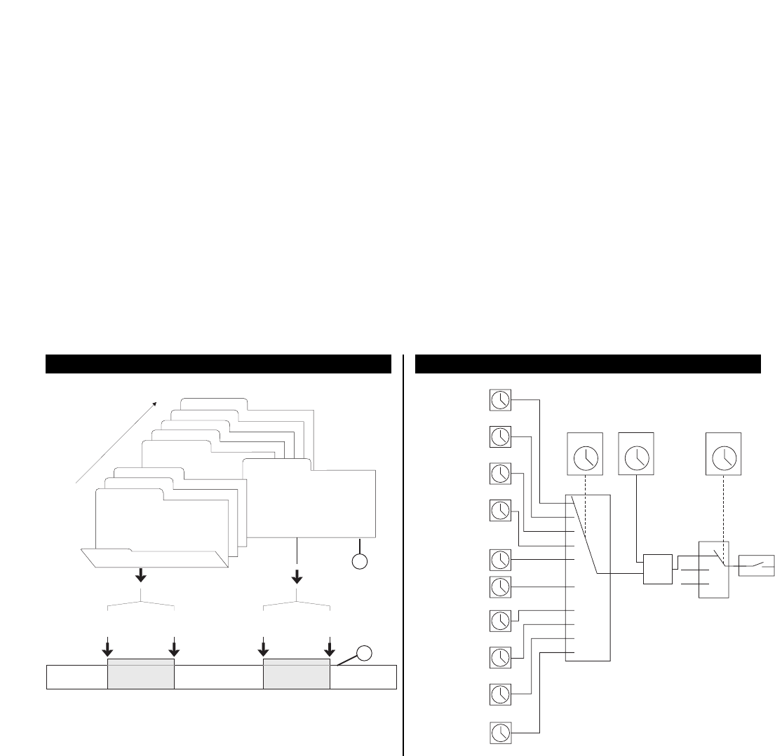
1.0 Description (page 64)
2.0 Features (page 64)
3.0 Application / Installation (page 65)
3.1 Safety instructions (page 65)
3.2 Installation instructions (page 65)
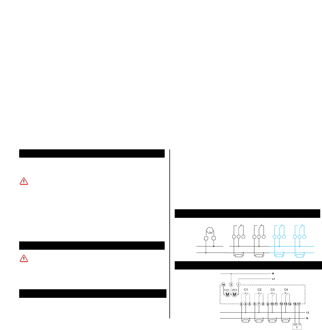
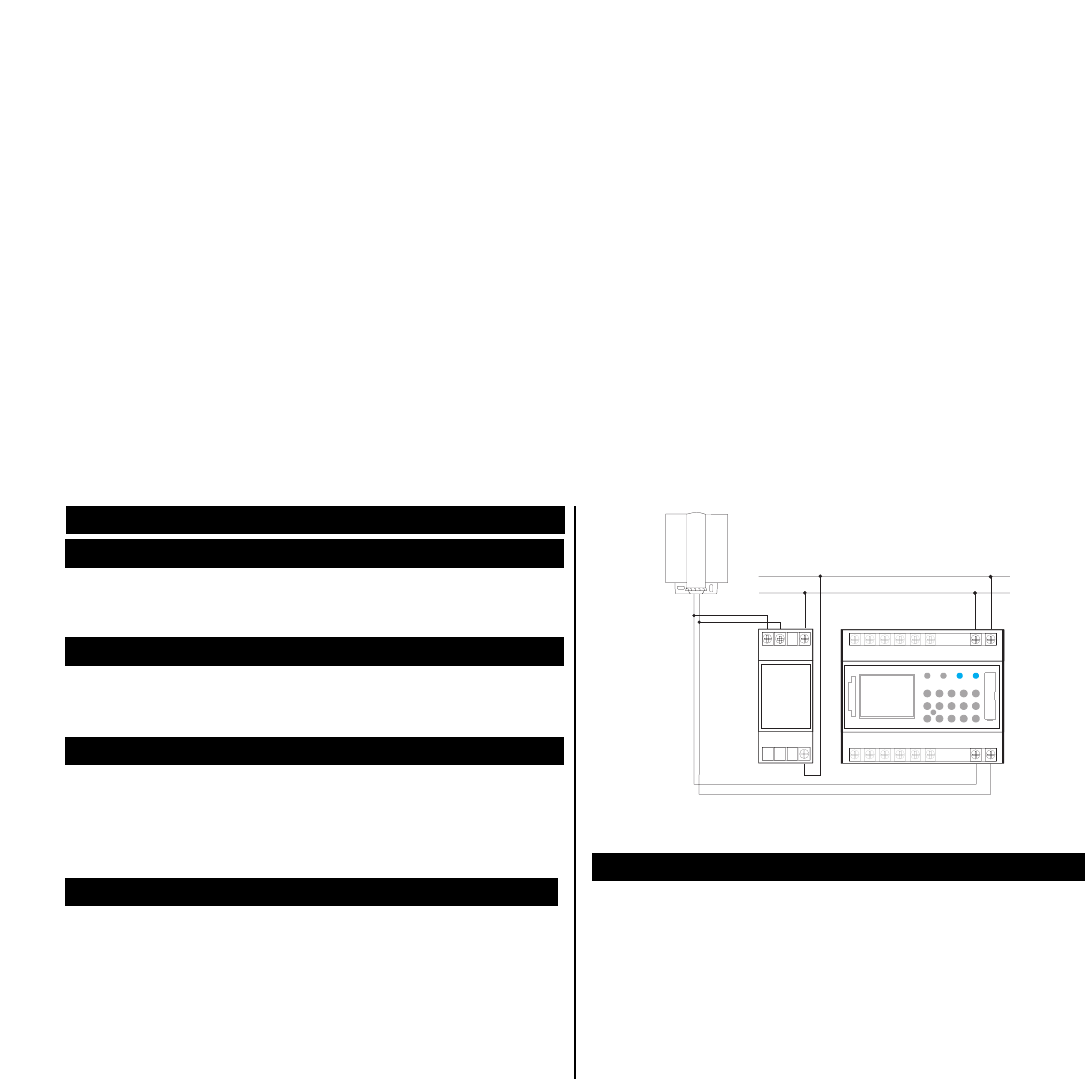
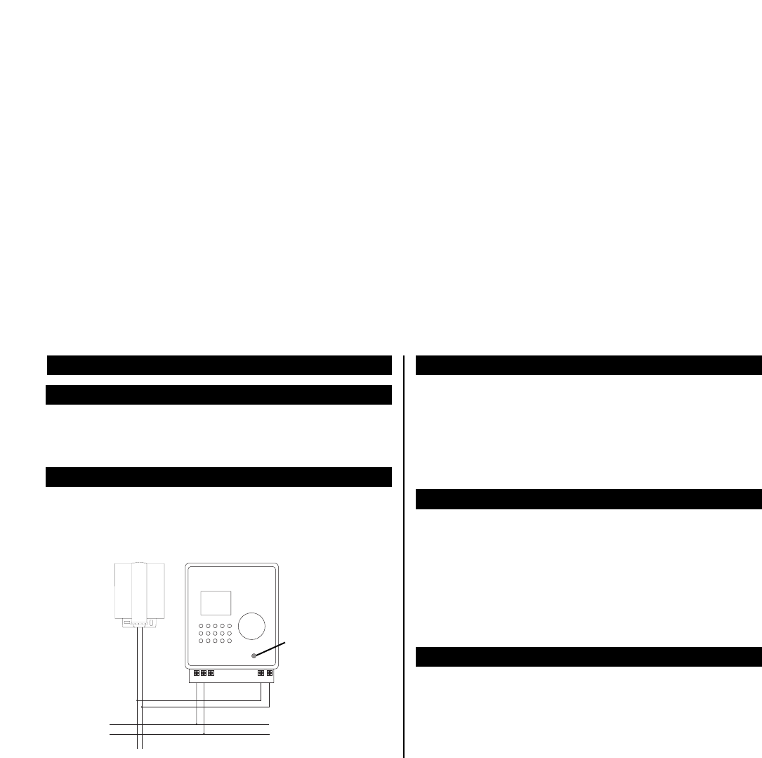
3.3 Electrical connection (page 65)
3.4 Technical data (page 66)
3.5 Dimensions illustration (page 67)
4.0 Power Reserve (page 67)
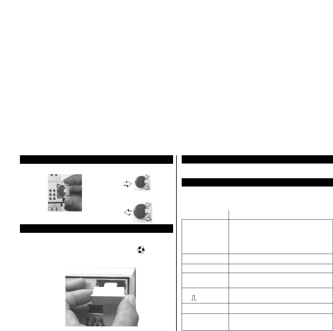
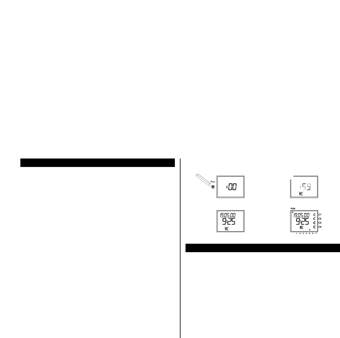
4.1 Battery loading (page 67)
4.2 Battery changing (page 67)
5.0 Initial Operation (page 68)
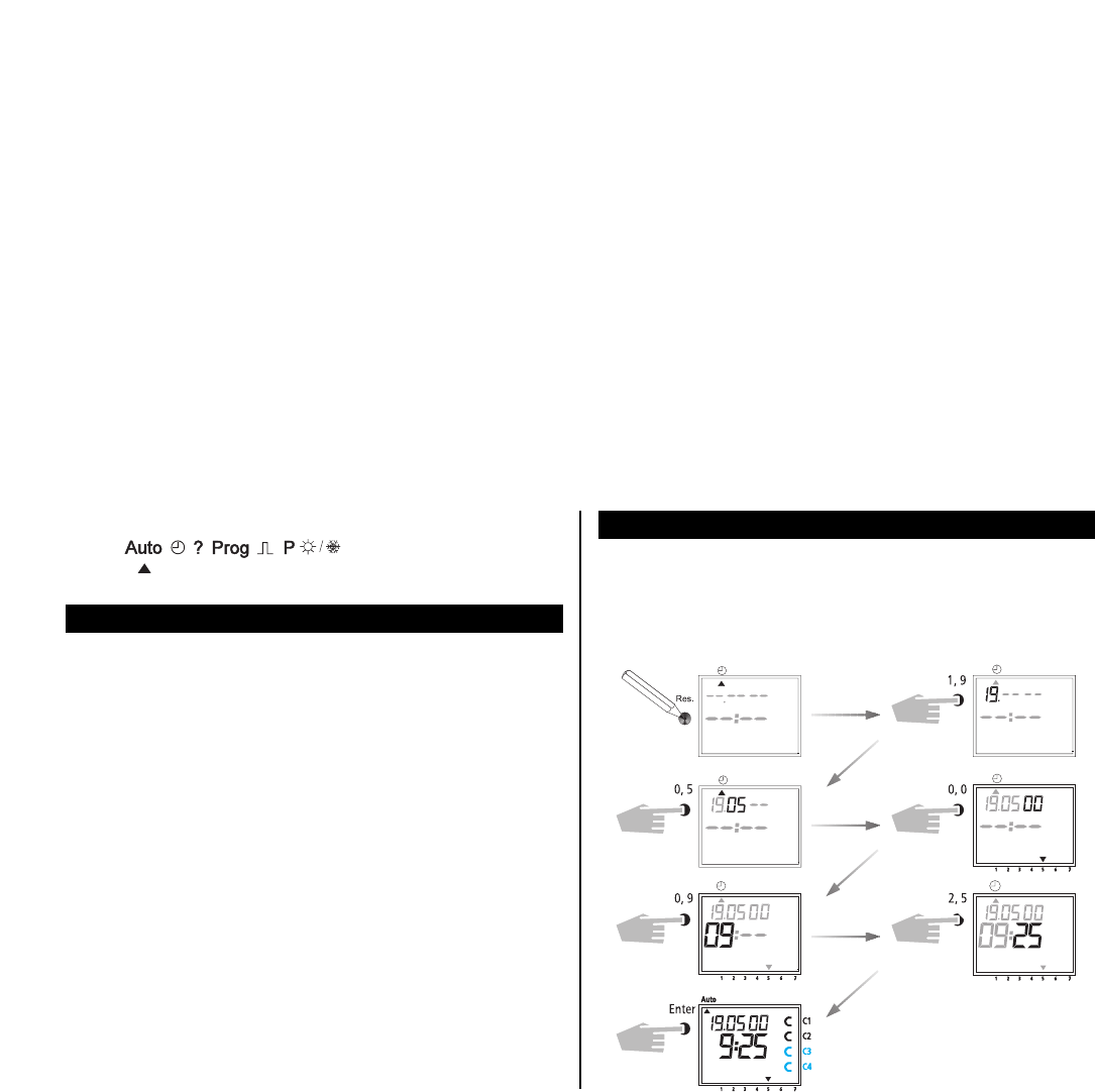
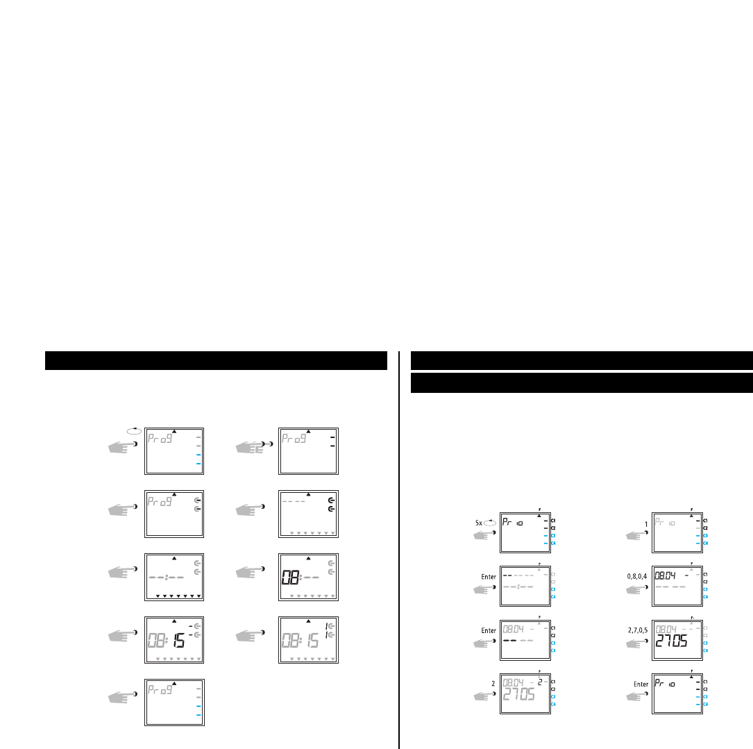
5.1 Overview of menu selection (page 68)
5.2 Entry adjustment (page 69)
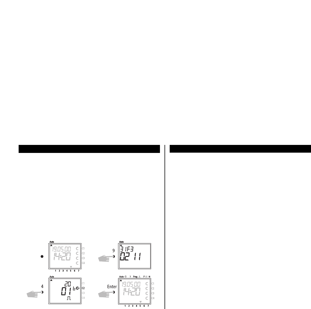
5.3 Setting date and time (page 69)
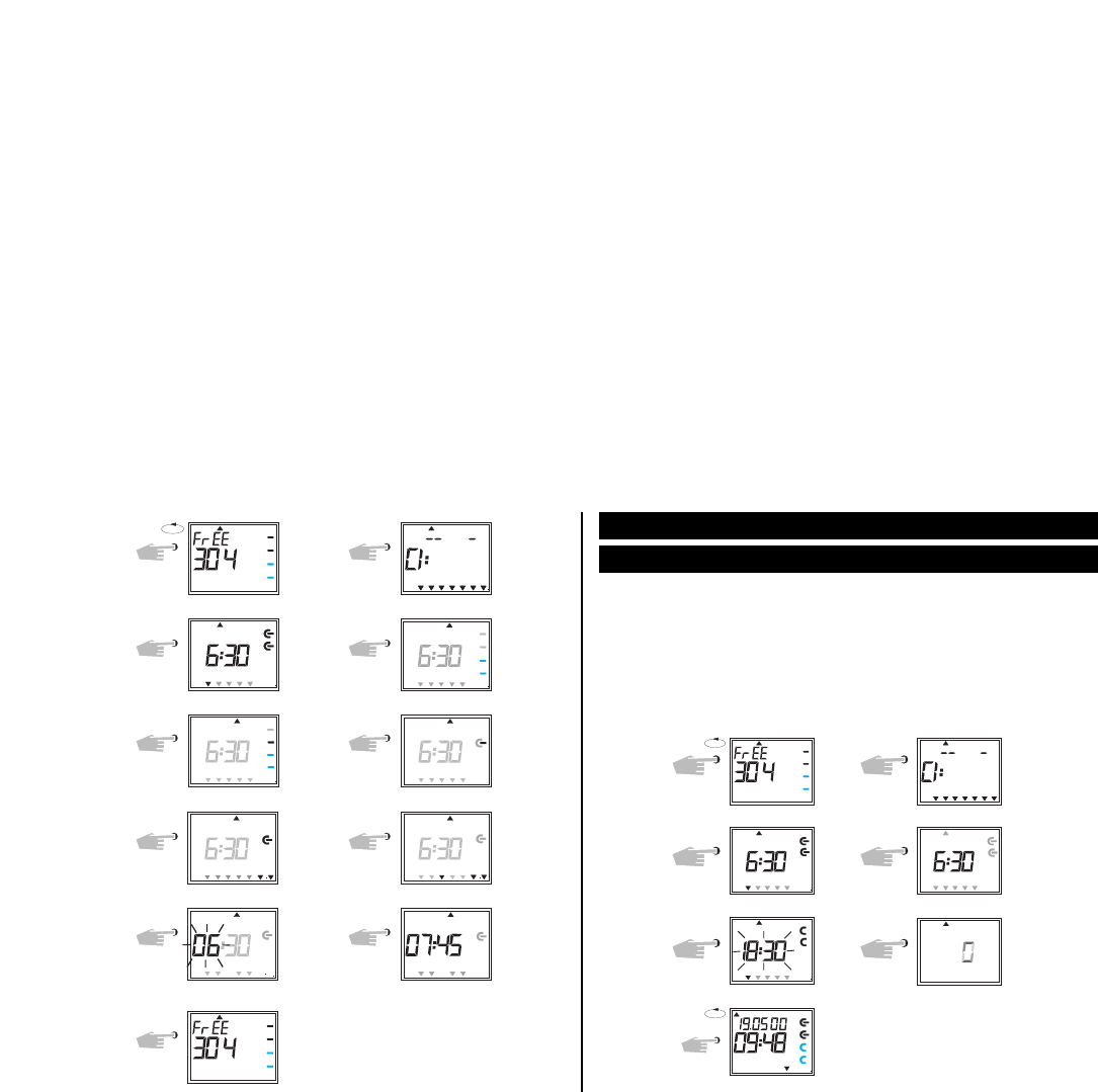
5.4 Selection schedule for automatic Summer/Winter time (page 70)
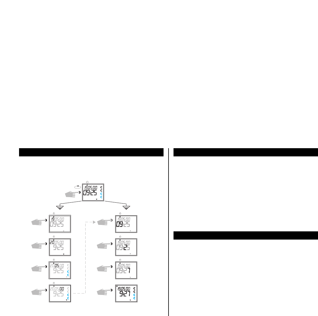
5.5 Changing automatic Summer/Winter time (page 70)
5.6 Changing date/time (page 71)’
5.7 Radio time switch (page 71)
5.8 Connection and adjustment of the radio antenna (page 71)
5.9 Initial operation of the radio time switch (page 74)
5.10 Forced transmitter call (page 74)
6.0 Manual Intervention in the Program (page 75)
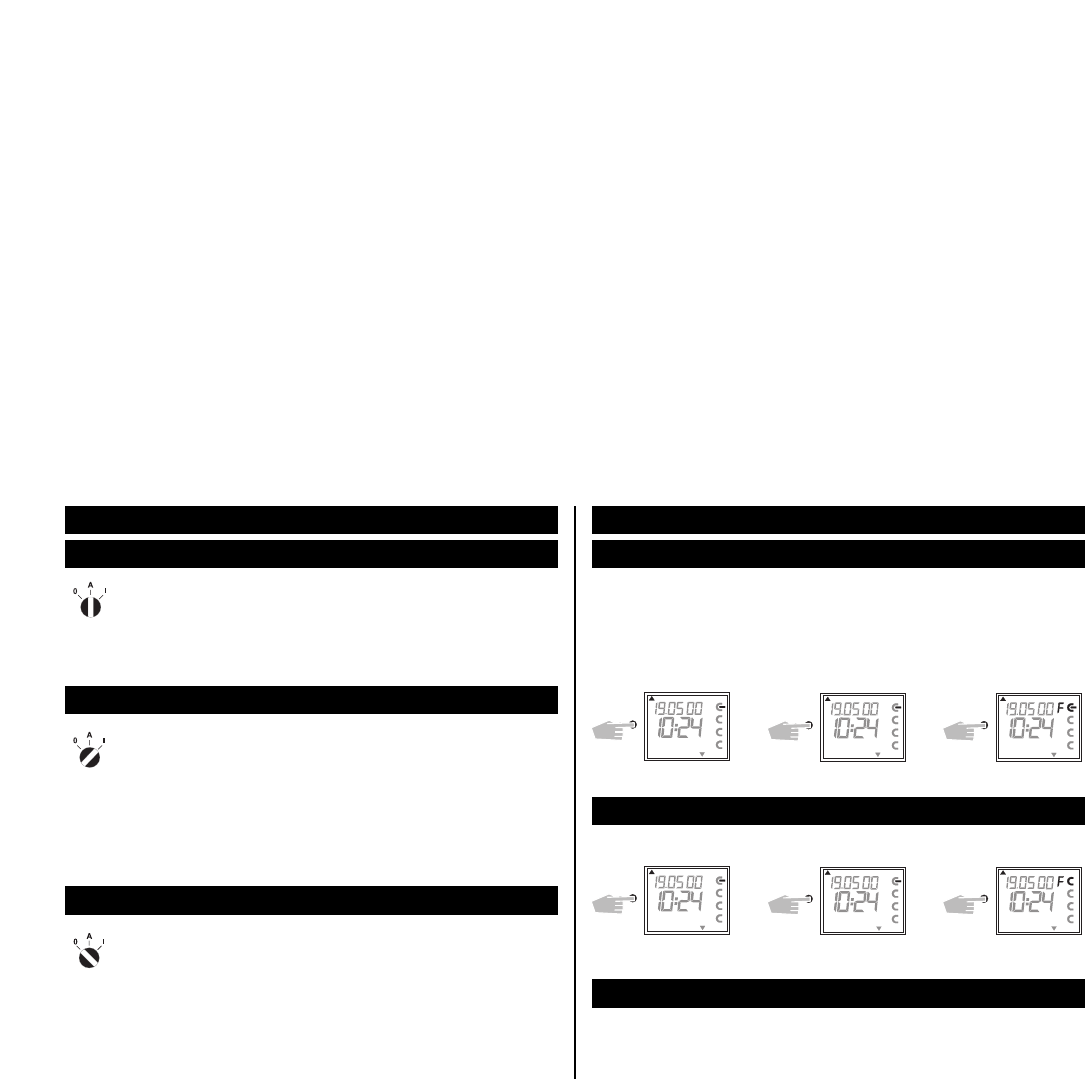
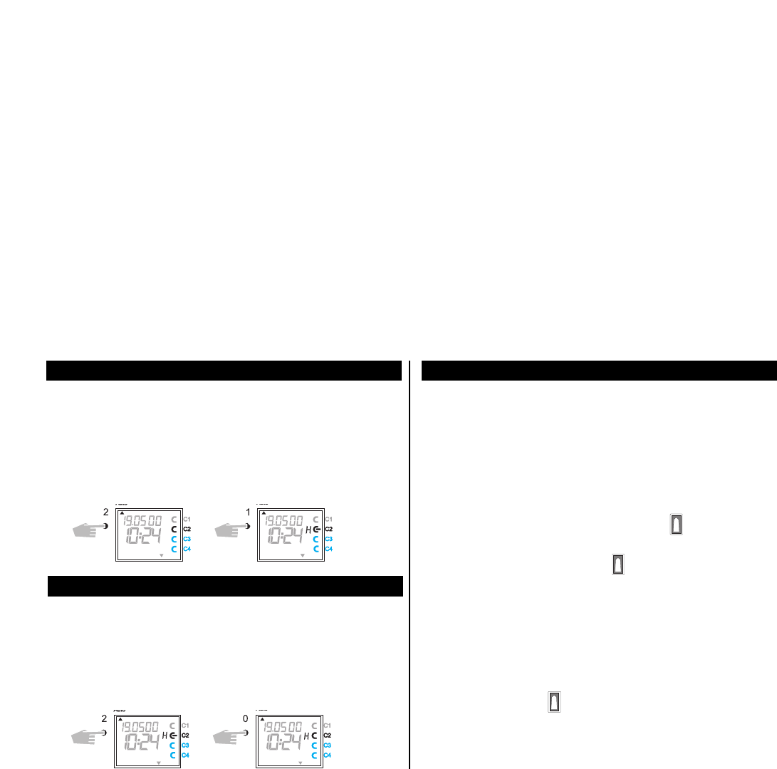
6.1 Permanent ON/OFF (page 75)
6.2 Manual ON/OFF (override switching) (page 75)
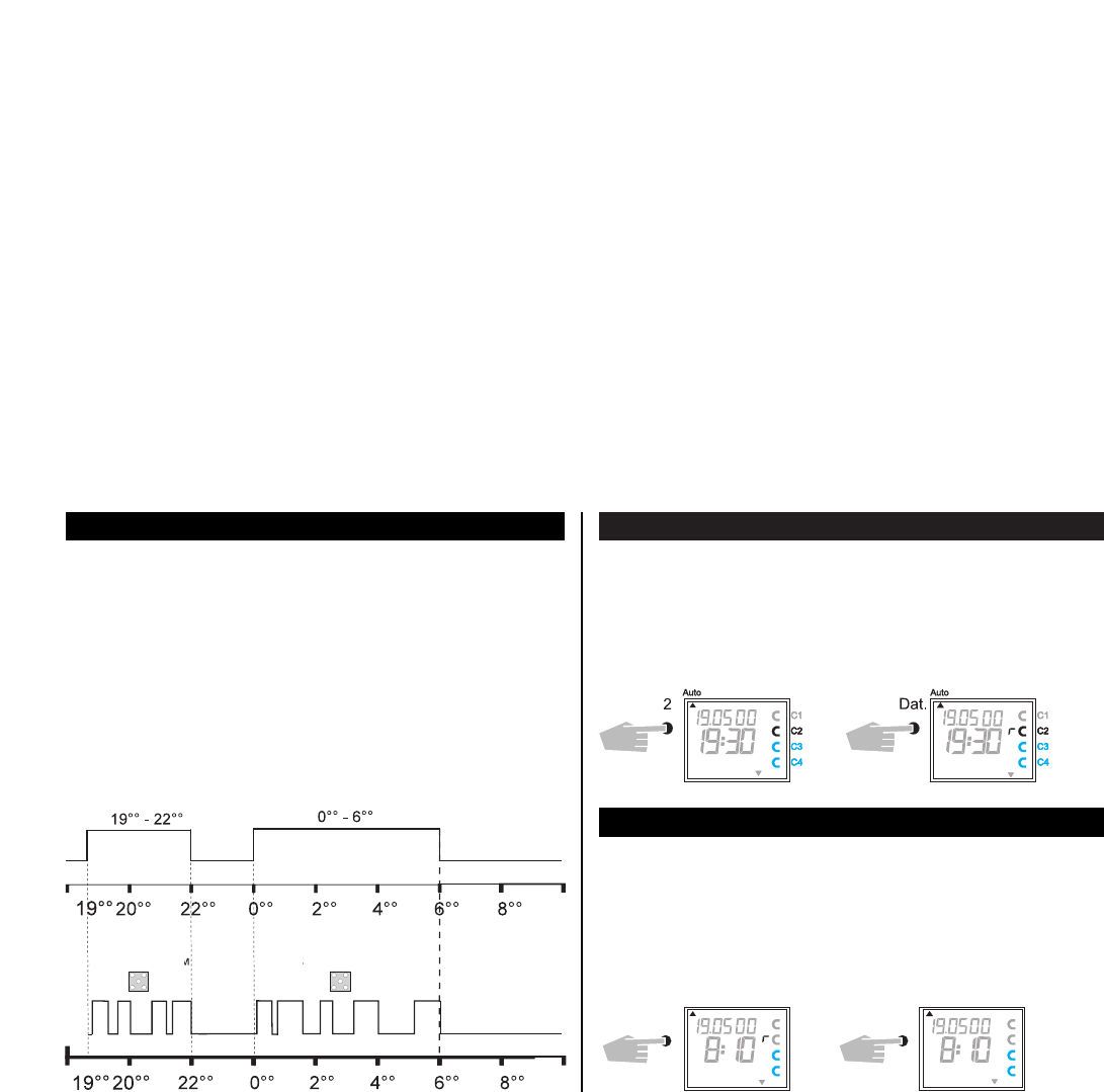
6.3 Random Program (page 75)
6.4 Random Program Start (page 76)
6.5 Stop Random program/override switching (page 76)
6.6 Locking/unlocking the keyboard (page 76)
6.7 Random Program (page 77)
6.8 Random Program start (page 77)
6.9 Stop Random Program / override switching (page 77)
7.0 Programming (page 78)
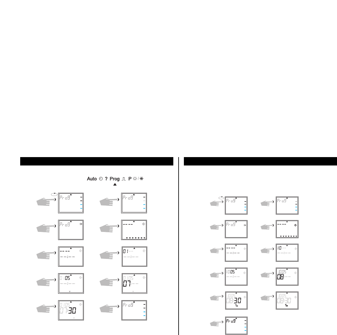
7.1 Programming weekly program (page 78)
7.2 Programming data program (page 79)
7.3 Programming single switching times (page 79)
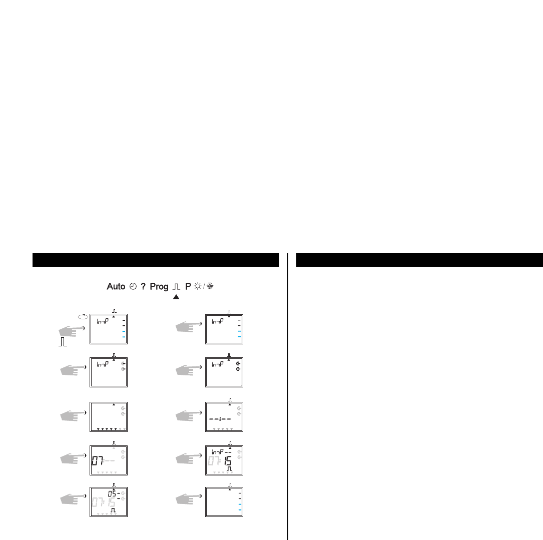
7.4 Programming pulse program (page 80)
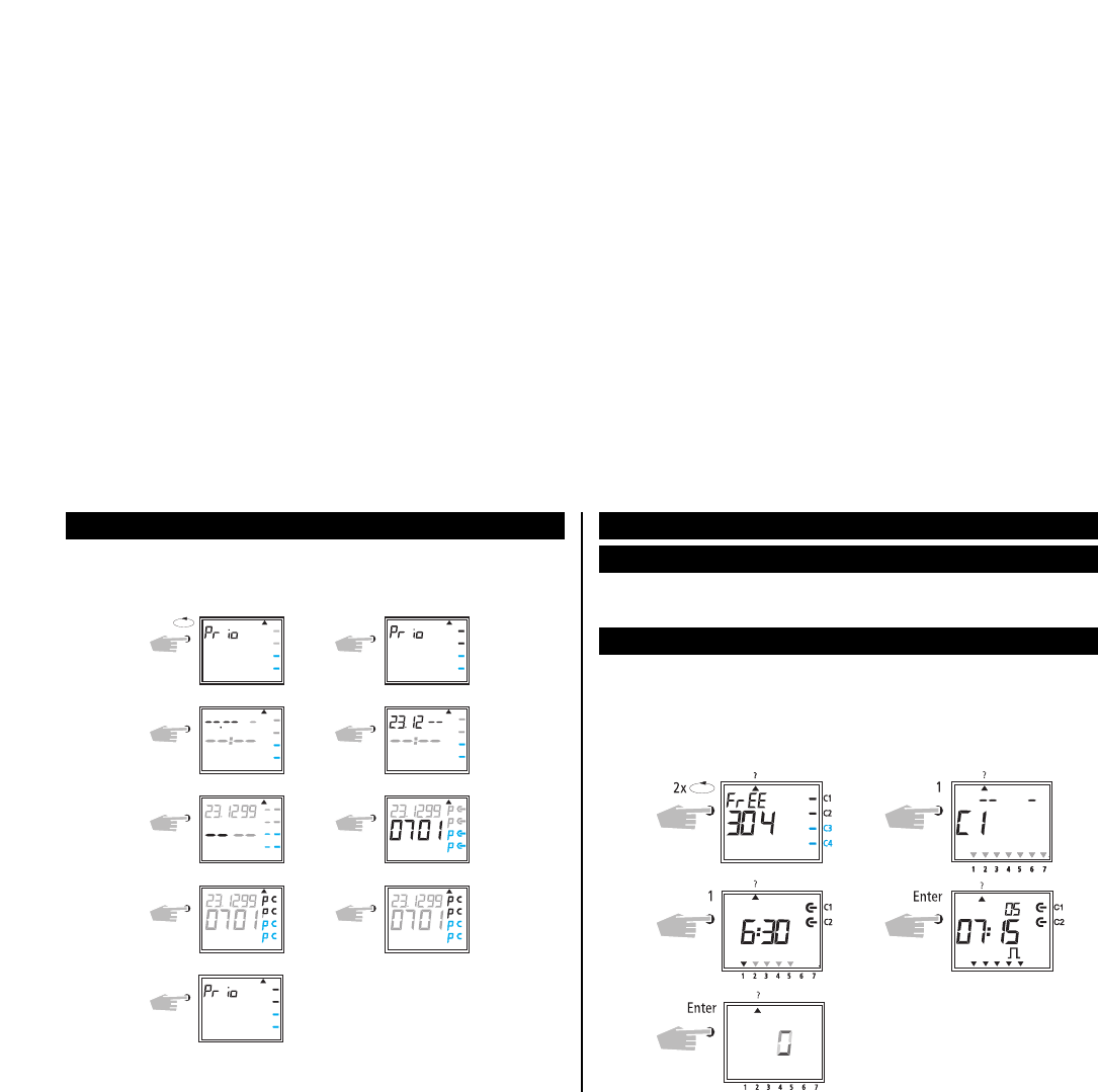
8.0 Priority program (page 80)
8.1 Programming weekly program with weekly program P1-P9 (page 82)
8.2 Setting time period for the weekly program (page 82)
A. Recurring annually (Seite 82)
B. Program only in specified year (Seite 83)
C. Stipulating public holiday without fixed date (Seite 83)
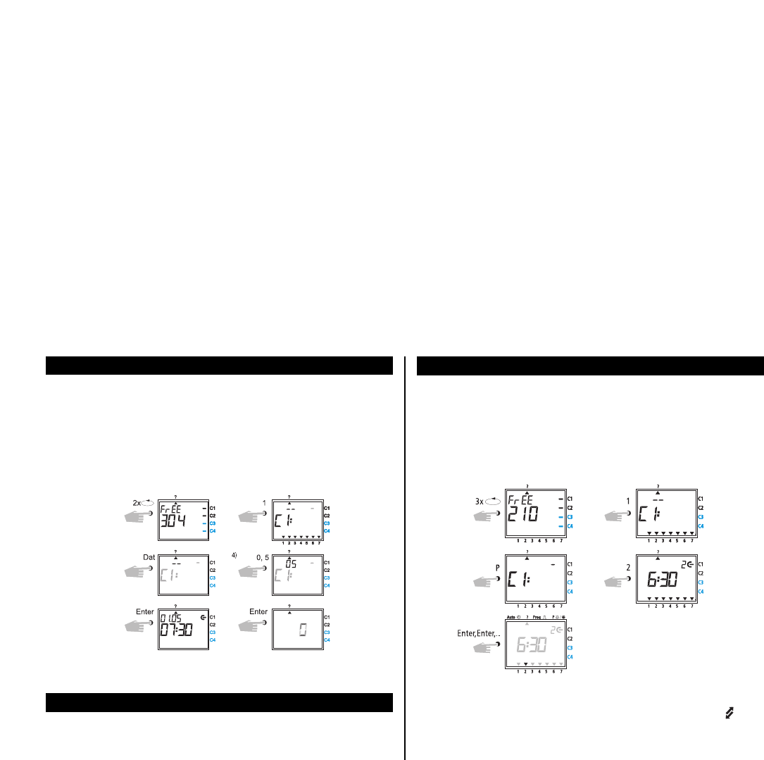
8.3 Time limited permanent switching (page 84)
9.0 Program Interrogation (page 84)
9.1 Whole program interrogation (page 84)
9.2 Interrogation of designated switching times (page 84)
9.3 Interrogation of channel related date program (page 85)
9.4 Interrogation of date completely (page 85)
9.5 Interrogating weeky program with priority (page 85)
9.6 Interrogation of version number/ features
of measurement impuls (page 86)
10.0 Changing a stored program (page 86)
11.0 Cancellation (page 87)
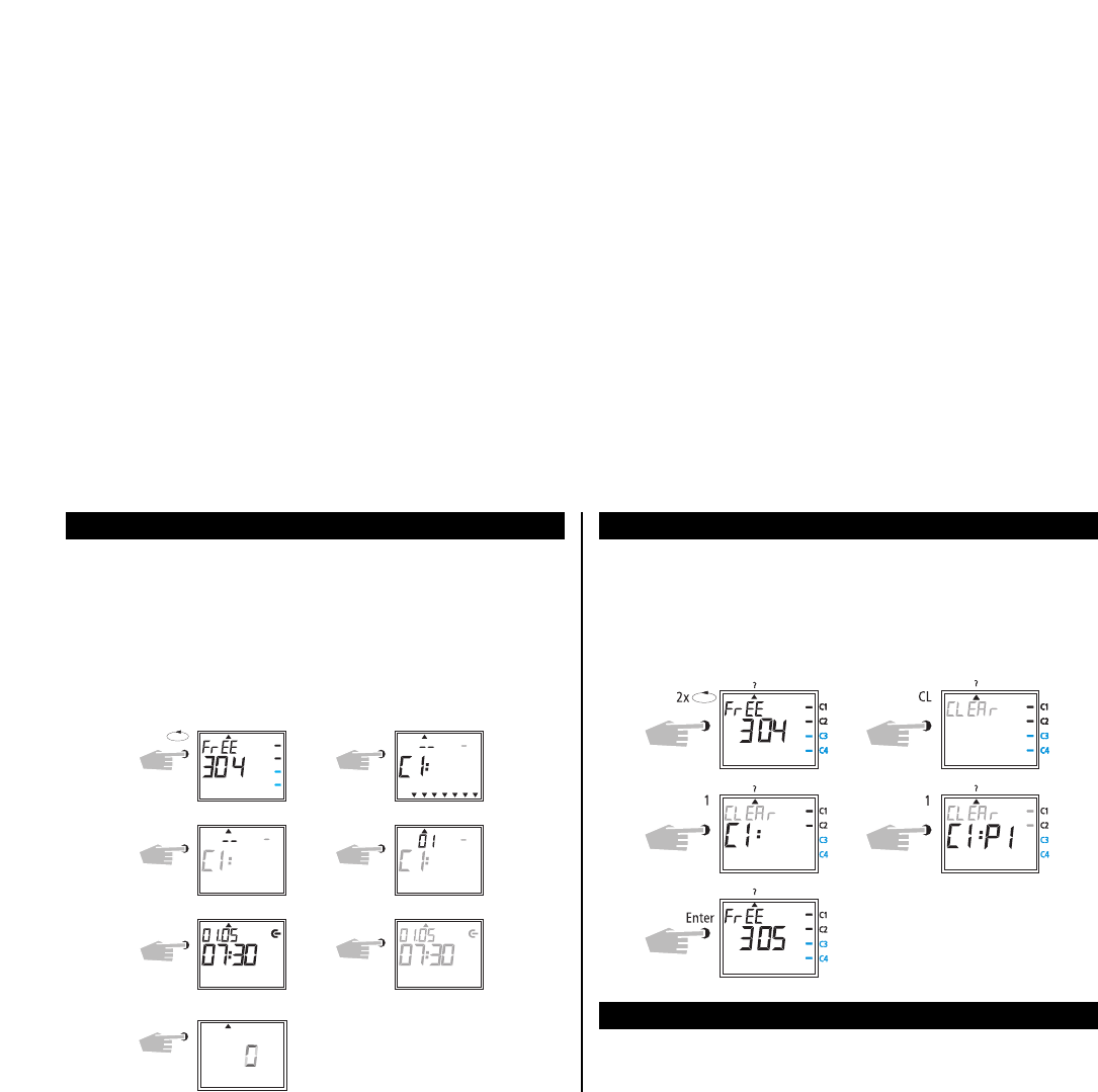
11.1 Cancellation of individual switching times (page 87)
11.2 Cancellation of date program (page 88)
11.3 Cancellation of priority program (page 88)
11.4 Cancellation channel by channel (page 88)
11.5 Cancel everything (page 89)
12.0 Data Exchange/External Data Security (page 89)
12.1 Recording data from time switch on the memory card (page 89)
12.2 Reading data from memory card into the time switch (page 89)
12.3 Preview programming with Software OBELISK (page 90)
13.0 Tips and Dodges (page 90)
14.0 Glossary (page 91)
15.0 Table of errors (page 92)
63
64
1.0 Description of the Product 2.0 Features
1 Display DCF 77 reception (only TR 642S/ TR 644S/ TR 686/ 4 DCF)
2 Display data exchange with Obelisk
3 Display hours
4 Interface Obelisk
5 Cursor for program selection
6 Display date day
7 Display date month
8 Display year
9 Random indicator /P 1 .. 9 / Manual ON (H
o / Manual OFF (H p)
10 Display status ON =
o OFF = p
11 Permanent switching OFF-AUTO-ON
12 Buttons 0 – 9 for program entry
13 Battery compartment
14 Button for entry of date switchings
15 Button for entry of priority programs/changes
16 Button for cancellation of programs and program steps
17 Connection terminal for DCF 77 antenna (only TR 642S/ TR 644S DCF)
18 Button for entry of input
19 RES = Reset / the micro-processor makes a defined new start
20 Program selection button for menu selection
21 Display for pulse programming
22 Cursor for display of days of the week 1 = Monday, 2 = Tuesday..
23 Display 1 x shows single switchings
24 Interface for infrared communication
25 LED lights up, if polarity has to be changed
– Yearly Time Switch
Time switch programming or PC programming using Windows from WIN 95 /
WIN 98 / WIN NT with Obelisk software
The time switch can be programmed up to 364 days in advance
– Data transfer and security possible with Obelisk storage card
Data can be transferred from time switch to time switch, from time switch to
PC and vice versa
– The Obelisk memory card allows you to prevent operation of the device by
unauthorized persons.
– 324 switchings for free block formation of channels and week days
– Permanent switching times by means of EEPROM
– Day/Week/Year program
– Random program
– Pulse program
– Switching times: ON or OFF delay
– 1x-function for all date-related switching times
– 10 priority programs consisting of 10 individual weekly programs per channel
Time limited permanent switching ON/OFF
Approx. 1,5 years battery reserve by means of exchangeable environmentally
friendly lithium cell
Option: TR 642S / TR 644 S radio controlled
– Up to 10 timers can be connected to the antenna
65
3.0 Application / Installation
Time switches switch ON, OFF and over connected electrical units, depending on
time, on a daily or weekly cycle and related to date.
The time switch may only be used in dry areas
Time switches are suitable for use in environmental conditions with nor-
mal pollution.
The time switch (TR 642 S – TR 644 S) is suitable for mounting on the
35 mm top-hat rail (DIN EN 50022)
TR 686/ 4 DCF timer is suitable for wall mounting
Wall mounting with installation kit 907 0 053 (only TR 642S-TR 644S)
3.1 Safety Instruction
The connection and installation of electrical equipment may be
effected only by a qualified electrician. National regulations
and any valid safety conditions should be observed.
Interference with and changes to the product will result in can-
cellation of the guarantee.
3.2 Installation Instructions
In spite of expensive protection measures, exceptionally strong magnetic
fields can lead to the destruction of the micro-processor controlled time
switch.
We therefore recommend attention be given to the following points before instal-
lation:
– Use separate lead for the mains voltage supply.
Suppress inductive loads with suitable RC filters.
Do not mount product in direct proximity to sources of interference as e. g.
transformers, contactors, PCs and TV and communication equipment.
After suffering intereference, we recommend, before re-setting, a RESET with a
new initial set up (chapter 5.3).
Strongly heat-generating products on the right side of the product shorten the
life of the battery.
3.3 Electrical Connection TR 642 S / TR 644 S
National regulati-
ons and any valid
safety conditions
must be observed.
1
4
7
10
3
6 9
12
2
5 8
11
L2
C1
C2 C3 C4
N
L
M
L1
N
N
TR 642S
TR 644S
TR 686/4 DCF
66
3.4 Technical Data TR 642 S – TR 644 S/ DCF
Description: Time-Switch with Year-program
Program Type: Day/ Week/ Year
Supply Voltage: 230 V~ ± 10 %
Nominal Frequency: 50 – 60 Hz
Power Consumption: Approx. 3 VA
Switching Capacity TR 642S/ DCF: 2 x 16 (10) A, 250 V~
Switching Capacity TR 644S/ DCF: 4 x 16 (10) A, 250 V~
Contact Material: AgSnO
2
Contact Type: Change-Over
Time Base: Quartz
Memory Locations: 324
Minimum Switching Time: 1 second/minute
Minimum Pulse: 1 second
Switching Accuracy: Accurate to the second
Accuracy: ± 1 sec./day at 20° C
Power Reserve TR 642S/ TR 644S: Lithium Cell 1,5 years at 20° C
Permissible Ambient Temperature: – 10° C ... + 50° C (–10T50)
Protection Class: II if installed according to EN 60335
Enclosure Type: IP 20 in accordance with EN 60529
Type: 1 BSTU in accordance with EN 60730-1, -2,- 7
For timers TR 642S -TR 644S DCF power supply 907 0 182 is necessary
Time Base: Radio exact
(with power reserve quartz operated)
Max. Distant of the radio antenna: 200 m
Enclosure Type: IP 54 in accordance with EN 60529
Max. Loading: 10 products.
Note deviating technical data on the rating plate
Rights to technical improvements are reserved.
Technical Data TR 686/ 4 DCF
Description: TR 686/ 4 DCF
Program Type: Day/ Week/ Year
Supply Voltage: 110/ 230 V~ ± 10 %
Nominal Frequency: 50 – 60 Hz
Power Consumption: Approx. 8 VA
Switching Capacity: 4 x 8 (2) A, 250 V~
Contact Material: AgSnO
2
Contact Type: Change-Over
Time Base: Quartz
Memory Locations: 324
Minimum Switching Time: 1 second/minute
Minimum Pulse: 1 second
Switching Accuracy: Accurate to the second
Accuracy: ± 0,5 sec./day at 20° C
Power Reserve: Lithium Cell 2,5 years at 20° C
Permissible Ambient Temperature: – 10° C ... + 50° C (–10T50)
Protection Class: II if installed according to EN 60335
Enclosure Type: IP 20 in accordance with EN 60529
Type: 1 BSTU in accordance with EN 60730-1, -2, - 7
TR 686/ 4 DCF
Time Base: Radio exact (with power reserve quartz operated)
Max. Distant of the radio antenna: 200 m
Enclosure Type: IP 54 in accordance with EN 60529
Note deviating technical data on the rating plate
Rights to technical improvements are reserved.
In the event of a power failure, the battery back-up provides for the main-
tenace of correct time (approx. 1.5 years). Even without power and with a
drained battery, the switching times remain permanently stored.
1. Note the polarity of the lithium battery.
2. Insert the lithium battery into the holder (see diagram 1).
3. Push the battery holder into the battery compartment
TR 642S / TR 644S see diagram 2 / TR 686/ 4 DCF see diagram 4.
4. Press the battery holder down, untl it audibly locates.
67
Important Instructions
Battery changing with mains voltage
All memorised program data is maintained
Battery changing without mains voltage
Note: date and time are lost.
1. Lift the battery draw with a suitable screw driver (see diagram 2).
2. Remove the lithium battery from the holder (see diagram 3).
3. Note the polarity of the new lithium cell.
4. Insert the Lithium battery into the holder (see diagram 1).
5. Push the battery holder into the battery compartment (see diagram 2).
6. Press the battery holder down until it audibly locates.
7. Dispose of lithium battery in an environmentally friendly way.
4.0 Power Reserve
4.1 Battery Loading
4.2 Battery Changing TR 642 S – TR 644 S/ DCF
dia. 1
3.5 Illustration of Dimensions
Note
The time switches conform to the European Regulations 73/23/EWG (low voltage
rules) and 89/336/EWG (EMV-Regulations).
If the time switches are used with other products in one installation, attention
must be given to ensure that the whole installation does not cause radio interfe-
rence.
TR642S
TR644S
TR642S DCF
TR644S DCF
TR684/ 4 DCF
68
5.0 Initial Operation
Ensure that the lithium battery is located (Chapter 4.1)
Auto (Automatic Program)
Programmed switching times determine the
switching programm
Switching override (Manual ON/OFF)
Random ON/OFF
n – Set / change date and time
? – Interrogate, change, cancel, completely cancel
Prog – Programming of date, weekly and 1x switching
times
– Programming of date, weekly pulses, 1x pulse,
ON and OFF switching delays
P e.g. public holiday, vacation, or holiday program
s/f – Programming and change of Summer/Winter time
switching
Cursor below symbol:
TR 642S - TR644S/ DCF
Battery changing TR 686/ 4 DCF
Fig. 1
Fig. 3
Fig. 2
1. Insert new battery holder into battery compartment
2. Press battery holder down until it audibly locates
3. Dispose of lithium battery in an environmentally friendly way
Fig. 4
5.1 Overview of menu selection
Press the v button to move the cursor .
The cursor moves eacht time a menu item button is pressed.
69
Ending Programming: use v button, and place cursor into following
position .
5.2 Entry Adjustment
The time switch contains a prompt facility. Follow the flashing symbols they show
the programming sequence.
Entry Adjustment:
What to do when a wrong value has been entered in error?
Cancel the program step again:
– press button CL = one step back
– press button CL repeatedly = repeated steps back
When wrong value flashes:
– enter correct value with buttons 0 .. 9
or when programming channels or week-days:
or in the event of a wrong entry:
– press the same button again
The wrong selected channel would be deaktivated.
Note:
Only the last entry will be cancelled
5.3 Setting Date and Time
On initial operation press button RES with a pointed object e.g.pencil,and after-
wards release it.
Initial operation of the Radio controlled Time switch see chapter 5.9.
Example:
The time switch is to be set up on 19.05.2000 at 9.25
date month
hour
store
date day
year
minute
70
5.4 Selection Schedule for Automatic Summer/Winter Time
Setting Commen- Commen- Area
cement cement
dat 0 no change no change
Use for radio
controlled version
dat 1 last Sunday last Sunday EU
in March in October
2 AM 3 AM 3 AM 2 AM
dat 2 last Sunday 4th Sunday
in March in October UK
1 AM 2 AM 2 AM 1 AM
dat 3 1st Sunday last Sunday North
in April in October America
2 AM 3 AM 3 AM 2 AM
dat 4 individual Summer/Winter time table,
programmable only with Obelisk software
Setting of automatic summer-/ wintertime change over
Select the adjustment rule for automatic summer-/ wintertime change
over from table 5.4.
Activating see chapter 5.4.
5.5 Changing Automatic Summer/ Winter Time
Default: TR 642S/ TR 644S/ TR 686/4 DCF: dat 0
Default: TR 642S/ TR 644 S: dat 1
Select the new switching time (Chapter 5.3)
Example: basic setting dat 1 (radio controlled version)
Change to: Summer-/ Wintertime adjustment for EU dat 0
0
Enter
Dat.
6x
Store
Adjust
Select
New dat 0
With button v return to the automatic programme.
71
5.6 Changing Date / Time
With the cursor in Pos. n, any flashing value, the actual time or date, can be
changed with the buttons 0 .. 9.
1
1
1
1
1
2
2
2
2
2
3
3
3
3
3
4
4
4
4
4
5
5
5
5
5
6
6
6
6
6
7
7
7
7
7
7
7
7
7
7
Auto
??
Dat. 0, 9
2
7
1X
2,0
Enter
Enter
Enter
1 2 3 4 5 6 7
C1
C1
C2
C2
C3
C3
C4
C4
press Enter repeatedly, until the cursor is below Auto
or follow the line and change the actual time
Select Dat
Date Day
Store month
Store year
Store
Adjust
Adjust
Hour
Change date e.g. from
19.5.2000 to 20.5.1998
Change time only e.g.
from 9.25 to 9.27
5.7 Radio Time Switch
The operation of the radio time switch is exactly the same as with the TR 644.The
correct time, date and Summer-/Wintertime change-over set themselves automa-
tically with me DCF 77 radio receiver.
Interesting Details:
Accuracy of the radio receiver +/– 1 sec. in 1,000,000 years
Transmitter location is Mainflingen near Frankfurt
Transmitting radius of the transmitter approx. 1000 km
Synchronisation is effected after initial setting-up and then daily at
night.
5.8 Connection and Adjustment of the Radio Antenna
We recommend the following mounting positions:
– outside the control box (at least 4 m away)
– under the roof
– or in a protected position out of doors
Avoid mounting positions near:
– radio transmitting installations
– radiological equipment
– television and personal computers
72
1. Use only t antenna No: 907 0 243 to the radio controlled time
switch
2. Use a 2 lead cable for connection
3. Attach antenna cable to the terminal, connect power supply NT DCF 77.
In this case, set the summer-/ winter change to the correct changeover standard,
see chapter 5.3/ 5.4
In this case, set the summer-/ winter change to the correct changeover standard,
see chapter 5.3/ 5.4
TR 642S - TR 644S DCF
A. Operation without DCF 77 radio reception
B. Operation with DCF 77 radio reception
C. Adjustment of one time switch to the radio antenna
D. Adjustment of the radio antenna
N
N
L
L
DCF 77
TR 641S .. TR 644 S DCF
N
L
DCF 77
907 0 182
NT DCF 77
Adjust the radio antenna in the direction
of Frankfurt a.M. until the built in LED
flashes every second.
1. Connect first one time switch to the operating voltage 230 V~.
2. Connect radio antenna to this time switch, polarity does not matter.
3. The connection of the other devices to t DCF antenna 907 0 243
may take the form of star, bus or tree topology.
4. Connect the other time switches to radio antenna.
5. However the LED lights up, polarity of this antenna connection must be changed.
6. Connect the other time switches to the operating voltage 230 V~.
D. Adjustment of up to 10 time switches to the radio antenna
73
In this case, set the summer-/ winter change to the correct changeover standard,
see chapter 5.3/ 5.4
In this case, set the summer-/ winter change to the correct changeover standard,
see chapter 5.3/ 5.4
N
L
max. 10
TR 686/ 4 DCF
2
1a
1
DCF 77DCF 77
LED
DCF-BUS
TR 686/ 4 DCF
A. Operation without DCF 77 radio reception
B. Operation with DCF 77 radio reception
LED
flashes, if the antenna
connection has to be
changed, or in case of
short circuit
Adjust the radio antenna in the direction of
Frankfurt a.M. until the built in LED flashes every
second.
1. Connect first one time switch to the operating voltage 230 V~ or 110 V~.
2. Connect radio antenna to this time switch, polarity does not matter.
3. The connection of the other devices to t DCF antenna 907 0 243
may take the form of star, bus or tree topology.
4. Connect the other time switches to radio antenna.
5. However the LED lights up, polarity of this antenna connection must be changed.
6. Connect the other time switches to the operating voltage 230 V~ or 110 V~.
1. Use only tantenna No: 907 0 243 to the radio controlled time
switch
2. In this case the polarity does not matter.
3. The antenna signal is a SELV voltage
4. National regulations and any safety conditions had to be observed
5. Connect the time switch to the operating voltage 230 V~ or 110 V~.-
C. Adjustment of one time switch to the radio antenna
D. Adjustment of up to 10 time switches to the radio antenna
E. Adjustment of the radio antenna
A. Setting-Up Automatically
Note: During synchronisation press no buttons!
The synchronisation test would be discontinued immediately.
To obtain a new start after this, RES button must be pressed again.
1. The display counts from 00 to 59 (see illustration 2)
Depending on the reception quality of the DCF 77 signal, this
procedure can be repeated several times.
2. If the time swtich has received the whole of signal, RC goes on
flashing.
Only after a further signal is received, does the RC symbol stop.
The status of the channels are displayed (see illustration 3).
The clock is now ready.
B. Setting-Up Manually
Tip: If the clock, on the initial set-up, does not synchronise even after
several attempts, possibly because of a disturbed reception signal,
we recommend setting-up as described in Chapter 5.3.
The clock will then try once more to synchronise itself on the signal,
during the night.
5.9 Initial Operation of the Radio Time Switch
74
5.10 Forced Transmitter Call
The synchronisation of the time switch is effected after the initial setting-up, then
daily between 1.58 and 3.13.
A radio synchronisation can be called up manually during the day
(transmitter call).
Start of the Transmitter Call
1. Press Dat Button for approx. 3 secs.
2. then release
The timeswitch synchronises itself on the DCF 77 signal.
In the LCD display can be seen:
The RC symbol flashes only during a DCF 77 synchronisation!
If the time switch has synchronised itself, a program review takes place.
The channels take on, afterwards, the specified switching positions,from the indi-
vidual program.
The RC symbol is permanently in the LCD display.
Example: The time switch has synchronised itself on 19.5.2000 at 9.25.
2)
3)
75
6.0 Manual Intervention in the Program
6.1 Automatic Operation (standard setting)
The channels take in the switching condition provided the stored time program.
6.2 Permanent ON
Each channel can be manually switched in each menu to permanently ON. A per-
manent switching has highest priority. The channel remains in the permanently
ON switching position until manually cancelled.
The status display in the LCD (p / o) is not adjusted.
6.3 Permanently OFF
Each channel can be manually switched in each menu to permanently OFF. A per-
manent switching has highest priority. The channel remains in the permanently
OFF switching position until manually cancelled.
The status display in the LCD (p / o) is not adjusted.
Time limited permanent switchings ON/OFF (see Chapter 8.3)
Manual Intervention in the Program TR 686/ 4 DCF
Permanent ON
Permanently OFF
Resetting manual programs
Once the setting has been cancelled by pressing button CL, the time switch per-
forms a program review, which involves checking the stored program and then
setting the correct switching status.
Each channel can be manually switched in each menu to permanently ON or
OFF. A permanent switching has highest priority.The channel remains in the per-
manently ON or OFF switching position until manually cancelled.
Example: Channel 1 permanent ON.
Channel 1
permanent
OFF
Channel 1
permanent
ON
76
6.4 Manual ON (override switching)
Each channel can be switched ON manually in the automatic program. In which
case, the symbol H = hand appears in the display.
An override switching is cancelled again by the next switching command. The H
display is turned off.
Select Channel: e.g. Button 1 = Channel C1, Button 2 = Channel C2 etc.
Select Status: Button 1 = Switch ON, Button 0 = Switch OFF
Example: Switch ON Channel C2 manually, press button 2, once (press 1).
Channel 2
ON
6.5 Manual OFF (override switching)
Each channel can be switched OFF manually in the automatic program.An overri-
de switching in the automatic program is corrected again by the next switching
command. (The H symbol is turned off).
Select Channel: e.g. Button 1 = Channel C1, Button 2 = Channel C2 etc.
Select Status: Button 1 = Switch ON, Button CL (reset channel) = Switch OFF
Example: Switch OFF Channel C2 manually, Button 2, press.
Auto Auto
Auto Auto
Channel 2
OFF
6.6 Locking/ unlocking the keyboard
Effect:
The
Obelisk memory card allows you to prevent operation of the device by unaut-
horized persons.
In this case time switch query and programming are impossible without the
Obelisk card.
Locking the keyboard:
1. Insert the Obelisk memory card into the data interface.
2. Press key 8 for approx. 3 secs until the Obelisk icon is flashing.
Operating the time switch
If after a button is pressed and the Symbol is blinking, the keyboard is locked.
1. Insert the Obelisk memory card into the data interface.
2. You can the select the desired program using the v key.
3. Now you can remove the memory card in order to continue programming.
When the time switch returns to auto mode, the keyboard is locked.
Canceling the keyboard lock
1. Insert the memory card into the data interface.
2. Press key 8 until the icon appears.
3. Press key 8 for approx. 3 secs until the icon disappears.
4. Remove the memory card.
Now the time switch can be operated again without obstruction.
77
6.7 Random Program
General Comment
A random program causes the time switch to switch ON or OFF at random bet-
ween one or more pairs of switchings (ON and OFF switching time).
Duration of the random ON and OFF switching time approx. 10 – 120 minutes.
The random program can be selected individually for each time channel.
Example:
Between 19.00 and 22.00 random ON (display:r)
Between 0.00 and 06.00 random ON (display:r)
Programmed switching pairs
Random
Program
Random
Program
6.8 Random Program Start
A random program can be switched ON manually in the automatic program (Auto)
at any time. It remains active until switched OFF (chapter 6.9).
Note: If the random program is active in a channel, the symbol r (random)
appears beside the channel.
Example: Switch ON random program in Channel C2.
Channel 2 Start random
6.9 Stop Random Program / override switchng
A random program override switching can be interrupted at any time.
After cancellation of the random program override switching,the time switch car-
ries out a program review. This causes the time switch to inspect the stored pro-
gram and then take up the correct switching status.
Example: Stop random program Channel C2
Note: The symbol r turns OFF
C1
C2
C3
C4
Auto
CL
C1
C2
C3
C4
Auto
2
Random Random OFF
1
1
1
2
2
2
3
3
3
4
4
4
5
5
5
6
6
6
7
7
7
C1C1
C1
C2
C1
C2
C3
C2
C3
C2
C4
C4
Prog
Prog
Prog
Prog
Prog
Prog
Prog
Prog
1,2 Enter
0
Enter
1, 2, 3, 4, 5
Enter 1, 8
3, 0
78
Example 2: Weekly program – set switch OFF time
Channels C1 and C2 are to switch OFF at 18.30 from Mon to Fri p
Additional programming as described, or back into the automatic program with
button v.
Channel 1 + 2 Confirm Channel
Week Days
Hours
Store
Switch OFF
Confirm days
Minutes
e.g.: Channels C1 and C2 are to switch on at 6.30 from Mon to Fri o
Place cursor in pos.
1
1
1
1
1
1
2
2
2
2
2
2
3
3
3
3
3
3
4
4
4
4
4
4
5
5
5
5
5
5
6
6
6
6
6
6
7
7
7
7
7
7
C1
C1
C1
C1
C2
C2
C2
C2
C3
C3
C4
C4
Prog
Prog
Prog
Prog
Prog
Prog
Prog
Prog
Prog
3x
Enter 1
1,2
1,2,3,4,5
Enter
Enter
0, 6
3,0
*
)
7.0 Programming
7.1 Weekly program, set switch ON time
Select Prog
Switch ON
Channel 1 + 2
Confirm days
Minutes
*) Press button 0
Switching time activated daily
Confirm Channel
Weekdays
Hours
Storage Program
1 2 3 4 5 6 7
C1
C2
C3
C4
C4
C4
C3
C3
C2
C2
C1
C1
C2 C2
C4
C4
Prog
Prog
Prog
Prog Prog
Prog Prog
Prog Prog
Prog
Prog
Enter
Enter
1
2
Dat
1, 0
0, 5 0, 8
3, 0 1
3x
Example: Channel C2, 1 switch ON on the 10.5 at 8.30
Note: Only date related switching times can be programmed with the
function 1x see illustration 10. Once the switching time is effected,
it cancels itself automatically at mid-night.
Additional programming as described or
back into the automatic program with
button v
7.3 Programming Single Switching Time
10)
79
Select Prog Channel 2
Confirm Channel ON
Date Date Day
Date Month
Hours
Minutes
1 x
Store
Example.: Channel C1 is to switch ON yearly on the 1.5 at 7.30
Place cursor in pos.
1 2 3 4 5 6 7
C1
C1
C1C1 C1
C1
C2
C2
C2C2 C2
C3
C3
C3C3 C3
C4
C4
C4C4 C4
Prog
Prog
Prog
Prog
Prog
Prog
Prog
Prog
Prog
Prog
Prog
Enter
1
1
Dat.
0, 1
0, 5 0, 7
3,0
Enter
3x
1x
7.2 Programming Date Program
Select Prog.
Channel 1
ON
Date Day
Hours
Store
Confirm Channel
Date
Date Month
Minutes
Additional programming as described or back into the automatic program with
button v.
8.0 Priority Program
80
With the Time Switch up to 9 different weekly programs can be
performed in addition to the normal weekly program. A firm weekly program
P1 ... P9 can be requested at any fixed periods of time.
That is, the programming consists of:
1. Setting the weekly program (see Chapter 8.1)
2. Setting commencement and completion date (see Chapter 8.2)
If the time period of several weekly programs cut across one another, the pro-
gram with the highest index number prevails e.g. weekly program P9 prevails
over weekly program P3.
In order to maintain control, we recommend that the various weekly programs
are noted in the table at the end of the user instructions.
Switching times are executed in the following order:
Permanent switching 6.0
Time limited permanent switching. Chapter 8.3 (out priority over ON).
1x switching times. Chapter 7.3.
Date switching times. Chapter 7.3 (out priority over ON).
Weekly program with priority. Chapter 8.2/8.3 (P9 priority over P1).
Weekly program. Chapter 7.1/7.2.
etc.
7.4 Programming Pulse Program
1
1
2
2
3
3
4
4
5
5
6
6
7
7
C1
C1 C1
C1
C1 C1
C2
C2 C2
C2
C2 C2
C3
C4
4X
Enter
1
1, 2, 3, 4, 5
0,7
1, 5
1 2 3 4 5 6 7
C1
C1
C1 C1
C2
C2
C2 C2
C3
C3
C4
C4
1,2
Enter
0, 5
Enter
Example: Channels C1 and C2 pulse duration: 5 secs from Mon to Fri at 7.15.
Place cursor in pos.
Select
Switch ON
Channel 1 + 2
Confirm Days
Minutes
Store
Confirm
Week Days
Hours
Pulse 5 sec.
Note After a time adjustment,pulses are only effected, which are programmed at
least one minute after the time adjustment.
81
Weekly Program Schedule with Priority Overview TR 642 S – TR 644 S
Highest Priority
weekly program P9
weekly program P8
weekly program P7
weekly program P6
weekly program P5
weekly program P3
weekly program P2
weekly program P1
weekly program P4
Channel C1 + C2 switch ON
Monday-Friday 6.30
pulse duration 5 secs.
Channel C1 + C2 switch ON
Monday-Friday at 7.15
pulse duration 5 secs.
Channel C1 + C2 at ON o
16.15 daily.
Channel C1 + C2 at OFF 20.00 p
Start
e.g. 8.4
Finish
e.g. 27.5
Start
e.g. 21.7
Finish
e.g. 7.9
Standard
Weekly Program
Weekly Program
P3
Standard
Weekly Program
Weekly Program
P4
Standard
Weekly Program
When changing to a new weekly program (e.g. on 8.4 at 0.00 hr), all channels in
questions are switched as if the new weekly program has been valid for some
time. This means the new weekly programme makes a review of the program.
8.1
8.2
EIN
AUS
Relais
P1
P2
P3
P4
P5
P6
P7
P8
P9
Standard
+
weekly program
„standard“
weekly program
„Priority
1“
weekly program
„Priority
2“
weekly program
„Priority
3“
weekly program
„Priority
4“
weekly program
„Priority
5“
weekly program
„Priority
6“
weekly program
„Priority
7“
weekly program
„Priority
8“
weekly program
„Priority
9“
Priority times
P1-P9
Date
switching
times
Permanently
ON/OFF
ON
OFF
RELAY
82
The time period of a weekly program P1 .. P9 is fixed by entering a commence-
ment and finishing date. The weekly program begins at 0.
00
on the commence-
ment date and ends at 24
00
on the finishing date.
Example: As opposed to the normally active program on Channel C1 from
8 April until 27 May, the individual priority program with index P2 is to beco-
me effective. In the fixed time period with priority sequence P1 .. P9, the whole
standard program (without priority sequence) is suppressed.
8.2 Setting Time Period for Weekly Program P1 .. P9
Additional programming as described or with button v back into the auto-
matic program.
7)
Select P
Channel 1
Date Start
Confirm
Confirm
Date end
Store
A. Recurring annually
Program 2
1
1
2
2
3
3
4
4
5
5
6
6
7
7
C1
C1
C1C1
C1
C1
C1 C1
C1 C1
C1 C1
C2
C2
C2C2
C2
C2
C2 C2
C2 C2
C2 C2
C3
C3
C3C3
C3
C3
C3 C3
C3 C3
C3 C3
C4
C4
C4C4
C4
C4
C4 C4
C4 C4
C4 C4
Prog
Prog
Prog
Prog
Prog
Prog
Prog
Prog
Prog
Prog
Prog
Prog
Prog
Enter
Enter
1
0
0, 8
1, 5
1
3x
1, 2
8.1 Programming Weekly Program with Priority P1 .. P9
Example Channel C1 and C2 switch on daily at 8.15
Weekprogram get priority sequence P1.
Note: Pulse switching times can also be
fixed with priority sequence. For
weekly programs with priority, any
number of ON/OFF switching com-
mands can be specified.
Select Prog Select Channel
Confirm
Switch ON
Daily
Hours
Minutes
Priority P1
Store
83
C1 C1C1 C1
C1
C2 C2C2 C2
C2
C3 C3C3 C3
C3
C4 C4C4 C4
C4
P
P
P
P
P
P
P
Enter
2,3,0, 4
Dat 2
Enter
5x
2
Example: Following this measure, a public holiday such as Easter 2000
(not a fixed date) will be activated automatically and will exe-
cute, e.g., program P2.
C. Stipulating public holidays without a fixed date
Select channel
Date start
Program 2
Confirm
Symbol
„no fixed date“
Confirm
Select P
Note: Programming of public holidays without fixed dates only needs to be carried
out once, e.g. following initial start-up.
This applies to holidays connected with Easter such as Ascension,Whitsun,
Corpus Christi, Ash Wednesday, Good Friday etc. Program the date of all of
these holidays that do not have a fixed date once only for the current
year.
C1 C1C1 C1
C1
C2 C2C2 C2
C2
C3 C3C3 C3
C3
C4 C4C4 C4
C4
P
P
P
P
P
P
P
Enter
8, 4, 0, 0
2, 7, 0, 5
2
Enter
5x
2
Example: Only in year 2000 from 8th April to 27th May, e.g. the weekly
program P2 activated.
B. Weekly program only in one specified year
Select channel
Date Start
and year
Priority 2
Confirm
End
Confirm
Select P
84
Menu Selection cursor under ?
By pressing ENTER button (several times) interrogate whole program.
9.0 Programe Interrogation
9.1 Whole Program Interrogation
9.2 Interrogating Only Designated Switching Times
1. Illustration: menu selection and display of the free memory locations e.g. 304
2. Illustration: e.g. select channel 1 (press button 1).
3. Illustration: begin interrogation e.g. from Mondays: button 0, 1 press.
(C2 is displayed likewise, as jointly programmed as a block).
Additional interrogation as
described, or back into the automatic
program with button v.
Select ?
Interrogate
Channel 1
From Day 1 = Mon
Interrogate
8.3 Time Limited Permanent Switching ON or OFF
E.g.: All connected equipment is to remain switched OFF during the Christmas
holidays between 23 December 1999 and the 7 January 2000.
C1 C1C1 C1
C1
C2 C2C2 C2
C2
C3 C3C3 C3
C3
C4 C4C4 C4
C4
P
P
P
P
P
P
P
P
P
Enter
2, 3,1, 2
9, 9
7, 0, 1
Enter
0
Enter
5x
1, 2
7)
Select P
Date Start
Channel1 .. 4
Date End
Switch OFF
Confirm
Year
permanent
Store
Additional programming as described or with button v back into the auto-
matic program.
85
9.5 Interrogating weekly program with priority
Fig. 1: Display of available memory space 210
Fig. 2: Select: Channel C1
Fig. 3: Only have priorities displayed
Fig. 4: Priority selection, have everything displayed with priority 2
Fig. 5: Press Enter to have further programs with priority 2 displayed
Select channel
Priority 2
Interrogate
Search priority
Selection
interrogation
Note: If, while in interrogation mode, a date, the year and the symbol are
displayed, then this indicates a public holiday without a fixed date.
To cancel: Press button v to return to the automatic program.
Illustration 1: Menu selection and display of the free memory locations e.g. 304
Illustration 2: Select Channel e.g. C1, press button 1
Illustration 3: Select date program, press button Dat
Illustration 4: Begin interrogation e.g. from May Button 0, press 5
(interrogation from February Button 0, press 2 etc.)
Illustration 5: Search for the desired switching time press Enter Button
e.g. on 1.5 Channel C1 ist urned on at 7.30
Illustration 6: Example, memory searches for additional switching times
The complete interrogation of the date program is effected as described in 9.3.
The entry step in illustration 4 (button 0,5) must be omitted in this case.
All stored date related switching times will be shown one after the other from
January (01).
9.4 Complete Interrogation of Date Program
9.3 Interrogation of Channel Related Date Program
With Buttonv back into the automatic program (Auto)
Select
Channel 1
From May
Interrogate
Date
Interrogate
86
Any program already stored,whether weekly or yearly can be changed depending
on individual requirements.
Condition: Cursor must be in the interrogation menu (?).
Example:
Illustration 1: example: free memory locatins 304
Illustration 2: Button 1 of selected Channel C1
Illustration 3: By repeatedly pressing the Enter Button, call up the switching
time to be changed
Illustration 4: Button P = adjustment
Illustration 5: e.g. Channels C2, C4 ON
– change channel sequence: with Button 1, 2, 3, 4
– afterwards store with Enter Button
– retain channel sequence: progress with Enter Button
Illustration 6: Store channel selection
Illustration 7: Switching status e.g. switch ON
– change switching status: with Button 0,1
– retain switching status: progress with Enter Button
Illustration 8: Programmed weekdays
– switching times are effected on the day, Mo to Fr (1 – 5)
– changing weekdays: e.g.: not Wed, Sat, Sun
press Button 3, 6, 7
– retain weekdays: progress with Enter Button
Illustration 9: Store change
Illustration 10: Change switching time: e.g. 7.45 press Button 7, 4, 5
– afterwards store with Enter Button
– retain switch time: progress with Enter Button
Illustration 11: Search for additional switching times, press Enter Button
10.0 Changing Stored Program
9.6 Interrogation of version number / features of measurement impuls
Example:
Interrogation:
Press button 9 for aprox. 4 secs., until fig. 2 appears.
fig. 1: automatic mode
fig. 2: displaying versionnumber of software (e.g. 0211)
fig. 3: 20 sec. duration of impuls measurement
01 min. = measurement every minute
fig. 4: back to automatic mode
fig. 1
fig. 3
fig. 2
4 sec.
button
87
1
1 1
1
1
2
2 2
2
2
3
3 3
3
3
4
4 4
4
4
5
5 5
5
5
6
6 6
6
6
7
7 7
7
7
C1 C1C1 C1
C1 C1
C1
C1
C2 C2C2 C2
C2 C2
C2
C2
C3 C3C3 C3
C3 C3
C3
C3
C4 C4C4 C4
C4 C4
C4
C4
Auto
?
?
?
?
?
1
CL
Enter
5X
2x
1
C1
C2
C3
C4
?
Enter
11.0 Cancellation
11.1 Cancellation of Individual Switching Times
Select ?
Day 1= Mo
Cancel
Confirm
suchen
Channel 1
Illustration 1: Menu selection ? and display of free memory locations e.g. 304.
Illustration 2: Select channel, e.g. C1, press Button 1.
Illustration 3: Commence search from day 1 = Monday, press Button 1.
Illustration 4: Search for switch times: press Enter Button.
Illustration 5: Cancel: press CL Button and then Enter Button.
Discontinue cancel procedure: press CL instead of Enter Button.
Illustration 6: Enter Button: memory searches for additional switching times.
Continue cancellation as described, or
back into the automatic program (Auto)
with button
v.
1
1
1
1
1
1
1
1
1
2
2
2
2
2
2
2
2
2
3
3
3
3
3
3
3
3
3
4
4
4
4
4
4
4
4
4
5
5
5
5
5
5
5
5
5
6
6
6
6
6
6
6
6
6
7
7
7
7
7
7
7
7
7
C1
C1
C1
C1
C1
C1
C1
C1
C1
C1
C1
C1
C2
C2
C2
C2
C2
C2
C2
C2
C2
C2
C2
C2
C3
C3
C3
C3
C3
C3
C3
C3
C3
C3
C3
C3
C4
C4
C4
C4
C4
C4
C4
C4
C4
C4
C4
C4
?
?
Prog
Prog
Prog
Prog
Prog
?
Prog
?
Enter, ..
1
Enter
3
Enter
Enter
P
0, 7, 4, 5
2x
1
Enter
C1
C2
C3
C4
?
1)
3)
Additional changes as described, or
back into the automatic program
(Auto) with Button v.
Select
Search
Channel
Confirm
Hours
Channel 1
Change
Confirm
Weekdays
Minutes
88
11.3 Cancellation of the Whole Priority Program
11.4 Complete Program Cancellation of One Channel
The program of one channel can be cancelled completely.
The cancellation is effected as described in Chapter 11.3. The entry step in
Illustration 4 (Button 1) must be omitted in this case.
4)
Illustration 1: Menu selection ? and display of free memory locations e.g. 304
Illustration 2: Initiate the cancellation procedure, press CL Button
Illustration 3: Select channel e.g. C1, press Button 1
Illustration 4: Select the priority program for cancellation e.g. P1, press Button 1
Discontinue cancellation procedure, press CL Button again
Illustration 5: Confirm cancellation procedure, press Enter Button
Additional cancellation as described, or
with Button back into the automatic
program (Auto) v.
Select
Channel 1
Cancel
Priority 1
Confirm
Cancellation
1 2 3 4 5 6 7
C1 C1C1 C1
C1 C1
C1 C1
C1
C2 C2C2 C2
C2 C2
C2 C2
C2
C3 C3C3 C3
C3 C3
C3 C3
C3
C4 C4C4 C4
C4 C4
C4 C4
C4
?
?
? ?
?
?
?
Dat
0, 1
z.B:
CL
Enter
2x
1
11.2 Cancellation of Dat Program
Illustration 1: Menu selection ? and display of free memory locations e.g. 304
Illustration 2: Select channel e.g. C1, press Button 1
Illustration 3: Select date switching times, press Dat Button
Illustration 4: Begin interrogation from January: press Button 0,1 (February 0,2 etc.)
Illustration 5: Search for the switching time to be cancelled, press Enter Button.
Illustration 6: Cancellation of the switching time: press CL Button and
afterwards Enter.
Illustration 7: Enter Button: memory searches for additional switching times.
Continue cancellation as described, or
back into the automatic program
(Auto) with Button v.
Select
Date
Search with Enter
Channel 1
Start Jan.
Cancel
Confirm
89
Switching times of time switch can be stored externally with the memory card.
The data can be filed or transferred from time switch to time switch.
12.0 Data Exchange / Security
Obelisk
C1
1234567
C2
C3
C4
theben
Obelisk
TR642S-TR644S
TR 686/ 4 DCF
No.
907 0 165
12.1 Entering Data from Timeswitch onto Obelisk Memory Card
Push the memory card into the data interface (Illus. 4). Select menu ?.
Enter data on the memory card: press Enter button.
The data is transferred when the End symbol is displayed in the LCD.
Remove memory card. Back into the Auto menu with Enter button.
12.2 Reading Data from Obelisk Memory Card into Time Switch
Push the memory card into the data interface (illus. 4).
Select menu Prog. Read data in, press Enter button. The data is transferred,
when the End symbol is displayed in the LCD.
Remove memory card. Back into the Auto menu with Enter button.
Note: If the program card Obelisk is removed too early, all programmed on/off
times are erased from the time switch (see table in chapter 16).
11.5 Cancel Everything
Illustration 1: Menu selection ? and display of free memory locations e.g. 304
Illustration 2: Cancel program, press Button CL
Illustration 3: Cancel everything, press Button 0
Discontinue cancellation, press CL Button again
Illustration 4: Confirm cancellation, press Enter Button
Illustration 5: Display 324 memory locations, all switching times are cancelled
With Button v back into the automatic program (Auto)
Select
Everything
Cancel
Confirm
Cancellation
chapter 4
2 x
90
13.0 Tipps and Additional Possibilities
1. Priority Program with Random Switching
Possibility for starting a random program automatically during public or annual
holiday times.
1. Program weekly program with the desired ON and OFF switching times and
priority sequence P1 .. P9 (Chapter 8.1)
2. Specifity the time period for the weekly program (Chapter 8.2).
3. Activate random program once manually (Chapter 6.7).
2. Special Program for holidays
Procedurally during holidays to switch ON and OFF connected units at different
times:
1. Program your desired holiday program. The ON and OFF switching times
must occur daily. A priority sequence P1..P9 must be assigned to the swit-
ching times (Chapter 8.1).
2. Specifity the time period for the weekly program
e.g. only for the 1st Maybegin 01.05 finish 01.05 (Chapter 8.2).
3. Pulse Program for Time delayed Switch-ONs
A switch-ON time e.g. at 7.0 and 10 secs can be achieved by:
1. programming a switch-ON time e.g. 7
00
ON (o) (Chapter 7.1)
2. Additional pulse program (Chapter 7.4) with same switch-ON time.
1. Switch-ON time e.g. 7
00
o
2. Additionally at 7
00
pulse OFF (p)
for the duration of 10 secs
3. Effective at 7
00
10 secs switch ON
12.3 Preview Programming with Obelisk Software
As an option, the possibility exists for preparing a program on the computer with
the software program. The prepared program can be written onto the memory
card and also be printed out.The memory card can now be as secure data or for
reading into another time switch of the type TR 686/ 4 or TR 641S .. 644S DCF.
Condition: PC from 486 free hard disk storage capacity approx. 1
MB
from WIN 95 / WIN 98 / WIN NT
Order No. 907 0 230 contains:
Obelisk software program + system adapter + Obelisk
memory card.
Schematic of
function
serial
or parallel
91
14.0 Glossary
What does automatic operation (Auto) mean?
The cursor is below Auto. Current time is displayed.
The switching sequence of the time switch is determined by the stored swit-
ching times. (Note: permanent switchng has priority see Chapters 6.2 and
6.3).
What is automatic return?
When in the interrogation or programming mode, if no button is used for a
long time, the display reverts automatically, after approx. 40 secs. to auto-
matic operation.The product then takes up the switching status specified by
the program.
Program recan?
This results in the time switch checking the stored program and implemen-
ting the correct switching condition.
What does entry correction mean?
In the event of wrong entry during programming, by pressing the CL button,
the entry can be cancelled and immediately corrected.
What does weekday block formation mean?
Simultaneous programming at one switching time e.g. 6
00
ON on several
days of the week e.g. Monday, Tuesday and Friday.
Only one memory lacation is used.
What does channel block formation mean?
Simultaneous programmed switching times, which are effective in several
channels, take up only one memory location.
Advantage: Faster programming of the switching times.
Note: After a time adjustment, only pulses, which are programmed at
least 1 minute after the time adjustment, are carried out.
4. Pulse Program for Time Delayed Switch-OFF
A switch-OFF time e.g. at 8.0 and 10 secs. can be achieved by:
1. Programming a switch-OFF time eg.g. 8
00
(Chapter 7.1)
2. Additional programming of a simultaneous pulse switching time of 10 secs.
duration.
1. Switch-OFF time e.g. 8
00
OFF p
2. Additional pulse ON (o) at 8
00
for
10 secs duration
3. Effective at 8
00
10 secs.
switch OFF.
Note: After time adjustment, only pulses, which are programmed at least 1
minute after the time adjustment are carried out.
5. Channel Block Formation
If not all memory locations are to be used, we recommend you dispense with
channel block formation when programming switching times.
This provides advantages when changing or cancelling individual switching
commands.
92
15.0 Table of errors
In order to increase the reliability of operation, several internal tests are run by
the time switch. If any error appears during these tests, the LCD will display the
following error numbers.
Error no. 4, 5, 6, 7:
Error in the transmittance of data memorized in the memory card.
1. Transfer program once again onto program card.
2. Repeat transaction.
3. Wrong type of time switch, e.g. memory card Obelisk is programed for
TR 642S, you try ro read into a TR 644S.
Error no. 3:
Program card has been withdrawn prior to end of data transfer.
Repeat transaction.
Error no. 1, 2, 8:
Program memory defect.
What does memory card mean?
Mobile data carrier can be used for:
– security of the programmed time program
– duplication of the programmed time program
– faster programming of additional time switches with the same program
Option only with software:
– programming on the PC, store on memory card
– read program into time switch(es)
– program print out possible
What does RESET mean?
By pressing the RESET button, a defined new start for the time switch is
effected.The current time and date are cancelled.The stored switching times
are maintained permanently.
What does EEPROM mean?
An EEPROM is an electronic memory, which can store memorised data even
without current (without battery back up) for a period of approx. 40 years.
What is an LCD?
An LCD display is a liquid crystal display, with which current time and stored
data (switching times) can be shown.
FIN
S
P
NL
N
I
GB
F
DK
CH
B
A
D
THEBEN-WERK Zeitautomatik GmbH
Postfach 56, D-72394 Haigerloch,
Telefon (0 74 74) 692-0, Telefax: (0 74 74) 692 150
Kundendienst: Tel. (0 74 74) 692-177, Fax (0 74 74) 692-207
Domain im Internet: http://www.theben.de
SIBLIK ELEKTRIK GES.M.B.H & CO.KG
Murbangasse 6, 1108 Wien, Tel. 01/68006-0, Fax. 6800659
TEMPOLEC International s.a.
Route de Biesme 49, B 6530 Thuin,
Tél. 071.59.00.39 (10 lignes), Fax. 071.59.01.61
WISAR WYSER + ANLIKER AG,
Steinackerstr. 29, CH-8302 Kloten,
Tel. 01/815 22 33, Fax. 01/815 22 60
BENNIKE + WANDER A/S
Hændværkerbyen 57, 2670 Greve
Tel. 02/43908000, Fax. 43690090
THEBEN S.A.R.L,
Zone Industrielle des Vignes, 32 – 38 Rue Bernard,
93012 Bobigny cédex, Tel. 01/49159700, Fax. 48445761
TIMEGUARD LTD.
Victory Park, 400 Edgware Road, London NW2 6ND
Tel. 0181/4508944; Fax: 0181/4525143
THEBEN S.R.L., via Ciro Menotti 11, 20129 Milano
Tel. 02/7386141/2/3/4, Fax. 7386144
GYLLING TEKNIKK A/S,
Rudsletta 91, P.O. Box 103, 1351 Rud,
Tel. (47) 67 15 14 00, Fax. (47) 67 13 87 85
ITHO B.V., P.O. Box 21, 3100 AA Shiedam
Tel. 010/4278500, Fax 010/4278882
DUARTE NEVES, L.D.A
mailto:ricardo@duarteneves.pt, http://www.duarteneves.pt
BOX: Apartado 52064, 1721-501 LISBOA, PORTUGAL
Tel: 351 21 754 1200, Fax: 351 21 754 1208 / 9
GYCOM Automation AB,
Box 1203, 18312 Täby, Tel. 08-56201100, Fax 08-7920654
SÄHKÖPALVELU THEBEN OY, Vattuniemenkatu 17,
PL 114, 00210 Helsinki,Tel. (09) 670 670, Fax (09) 670 410
1

Brauchen Sie Hilfe? Stellen Sie Ihre Frage.

Forenregeln

Missbrauch melden von Frage und/oder Antwort

Libble nimmt den Missbrauch seiner Dienste sehr ernst. Wir setzen uns dafür ein, derartige Missbrauchsfälle gemäß den Gesetzen Ihres Heimatlandes zu behandeln. Wenn Sie eine Meldung übermitteln, überprüfen wir Ihre Informationen und ergreifen entsprechende Maßnahmen. Wir melden uns nur dann wieder bei Ihnen, wenn wir weitere Einzelheiten wissen müssen oder weitere Informationen für Sie haben.

Art des Missbrauchs:

Zum Beispiel antisemitische Inhalte, rassistische Inhalte oder Material, das zu einer Gewalttat führen könnte.

Beispielsweise eine Kreditkartennummer, persönliche Identifikationsnummer oder unveröffentlichte Privatadresse. Beachten Sie, dass E-Mail-Adressen und der vollständige Name nicht als private Informationen angesehen werden.

Forenregeln

Um zu sinnvolle Fragen zu kommen halten Sie sich bitte an folgende Spielregeln:

Neu registrieren

Registrieren auf E - Mails für Theben TR 642 S wenn:


Sie erhalten eine E-Mail, um sich für eine oder beide Optionen anzumelden.


Andere Handbücher von Theben TR 642 S

Theben TR 642 S Bedienungsanleitung - Deutsch - 36 seiten


Das Handbuch wird per E-Mail gesendet. Überprüfen Sie ihre E-Mail.

Wenn Sie innerhalb von 15 Minuten keine E-Mail mit dem Handbuch erhalten haben, kann es sein, dass Sie eine falsche E-Mail-Adresse eingegeben haben oder dass Ihr ISP eine maximale Größe eingestellt hat, um E-Mails zu erhalten, die kleiner als die Größe des Handbuchs sind.

Ihre Frage wurde zu diesem Forum hinzugefügt

Möchten Sie eine E-Mail erhalten, wenn neue Antworten und Fragen veröffentlicht werden? Geben Sie bitte Ihre Email-Adresse ein.


Info