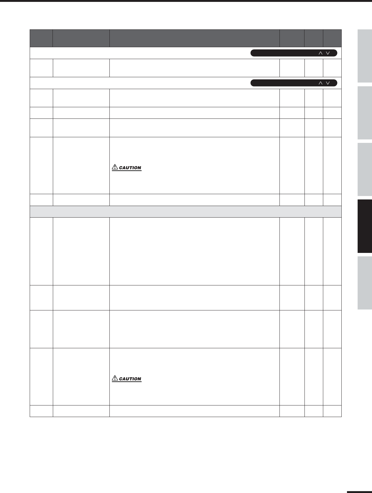
This product utilizes batteries or an external power supply
(adapter). DO NOT connect this product to any power supply or
adapter other than one described in the manual, on the name
plate, or specifically recommended by Yamaha.
WARNING: Do not place this product in a position where any-
one could walk on, trip over ,or roll anything over power or con-
necting cords of any kind. The use of an extension cord is not
recommended! If you must use an extension cord, the minimum
wire size for a 25’ cord (or less ) is 18 AWG. NOTE: The smaller
the AWG number ,the larger the current handling capacity. For
longer extension cords, consult a local electrician.
This product should be used only with the components supplied
or; a cart, rack, or stand that is recommended by Yamaha. If a
cart, etc., is used, please observe all safety markings and
instructions that accompany the accessory product.
SPECIFICATIONS SUBJECT TO CHANGE:
The information contained in this manual is believed to be cor-
rect at the time of printing. However, Yamaha reserves the right
to change or modify any of the specifications without notice or
obligation to update existing units.
This product, either alone or in combination with an amplifier
and headphones or speaker/s, may be capable of producing
sound levels that could cause permanent hearing loss. DO NOT
operate for long periods of time at a high volume level or at a
level that is uncomfortable. If you experience any hearing loss or
ringing in the ears, you should consult an audiologist.
IMPORTANT: The louder the sound, the shorter the time period
before damage occurs.
Some Yamaha products may have benches and / or accessory
mounting fixtures that are either supplied with the product or as
optional accessories. Some of these items are designed to be
dealer assembled or installed. Please make sure that benches
are stable and any optional fixtures (where applicable) are well
secured BEFORE using.
Benches supplied by Yamaha are designed for seating only. No
other uses are recommended.
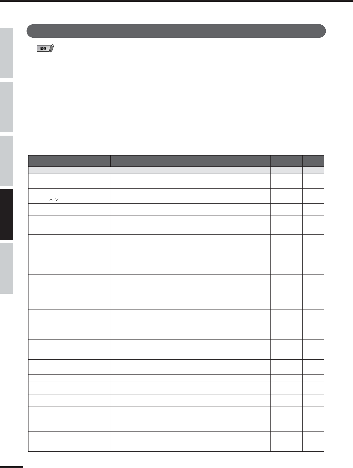
NOTICE:
Service charges incurred due to a lack of knowledge relating to
how a function or effect works (when the unit is operating as
designed) are not covered by the manufacturer’s warranty, and
are therefore the owners responsibility. Please study this manual
carefully and consult your dealer before requesting service.
ENVIRONMENTAL ISSUES:
Yamaha strives to produce products that are both user safe and
environmentally friendly. We sincerely believe that our products
and the production methods used to produce them, meet these
goals. In keeping with both the letter and the spirit of the law, we
want you to be aware of the following:
Battery Notice:
This product MAY contain a small non-rechargeable battery
which (if applicable) is soldered in place. The average life span
of this type of battery is approximately five years. When replace-
ment becomes necessary, contact a qualified service represen-
tative to perform the replacement.
This product may also use “household” type batteries. Some of
these may be rechargeable. Make sure that the battery being
charged is a rechargeable type and that the charger is intended
for the battery being charged.
When installing batteries, do not mix batteries with new, or with
batteries of a different type. Batteries MUST be installed cor-
rectly. Mismatches or incorrect installation may result in over-
heating and battery case rupture.
Warning:
Do not attempt to disassemble, or incinerate any battery. Keep
all batteries away from children. Dispose of used batteries
promptly and as regulated by the laws in your area. Note: Check
with any retailer of household type batteries in your area for bat-
tery disposal information.
Disposal Notice:
Should this product become damaged beyond repair, or for
some reason its useful life is considered to be at an end, please
observe all local, state, and federal regulations that relate to the
disposal of products that contain lead, batteries, plastics, etc. If
your dealer is unable to assist you, please contact Yamaha
directly.
NAME PLATE LOCATION:
The name plate is located on the rear of the product. The model
number, serial number, power requirements, etc., are located on
this plate. You should record the model number, serial number,
and the date of purchase in the spaces provided below and
retain this manual as a permanent record of your purchase.
Model
Serial No.
Purchase Date
SPECIAL MESSAGE SECTION
01X Owner’s Manual
3
1. IMPORTANT NOTICE: DO NOT MODIFY THIS UNIT!
This product, when installed as indicated in the instructions
contained in this manual, meets FCC requirements. Modifi-
cations not expressly approved by Yamaha may void your
authority, granted by the FCC, to use the product.
2. IMPORTANT:When connecting this product to accessories
and/or another product use only high quality shielded cables.
Cable/s supplied with this product MUST be used. Follow all
installation instructions. Failure to follow instructions could
void your FCC authorization to use this product in the USA.
3. NOTE: This product has been tested and found to comply
with the requirements listed in FCC Regulations, Part 15 for
Class “B” digital devices. Compliance with these require-
ments provides a reasonable level of assurance that your use
of this product in a residential environment will not result in
harmful interference with other electronic devices. This
equipment generates/uses radio frequencies and, if not
installed and used according to the instructions found in the
users manual, may cause interference harmful to the opera-
tion of other electronic devices. Compliance with FCC regula-
tions does not guarantee that interference will not occur in all
installations. If this product is found to be the source of inter-
ference, which can be determined by turning the unit “OFF”
and “ON”, please try to eliminate the problem by using one of
the following measures:
Relocate either this product or the device that is being
affected by the interference.
Utilize power outlets that are on different branch (circuit
breaker or fuse) circuits or install AC line filter/s.
In the case of radio or TV interference, relocate/reorient the
antenna. If the antenna lead-in is 300 ohm ribbon lead,
change the lead-in to co-axial type cable.
If these corrective measures do not produce satisfactory
results, please contact the local retailer authorized to distrib-
ute this type of product. If you can not locate the appropriate
retailer, please contact Yamaha Corporation of America,
Electronic Service Division, 6600 Orangethorpe Ave, Buena
Park, CA90620
The above statements apply ONLY to those products distrib-
uted by Yamaha Corporation of America or its subsidiaries.
* This applies only to products distributed by YAMAHA CORPORATION OF AMERICA.(class B)
FCC INFORMATION (U.S.A.)
4
01X Owner’s Manual
PRECAUTIONS
PLEASE READ CAREFULLY BEFORE PROCEEDING
* Please keep this manual in a safe place for future reference.
WARNING
Always follow the basic precautions listed below to avoid the possibility of serious injury or even death from
electrical shock, short-circuiting, damages, fire or other hazards. These precautions include, but are not limited to,
the following:
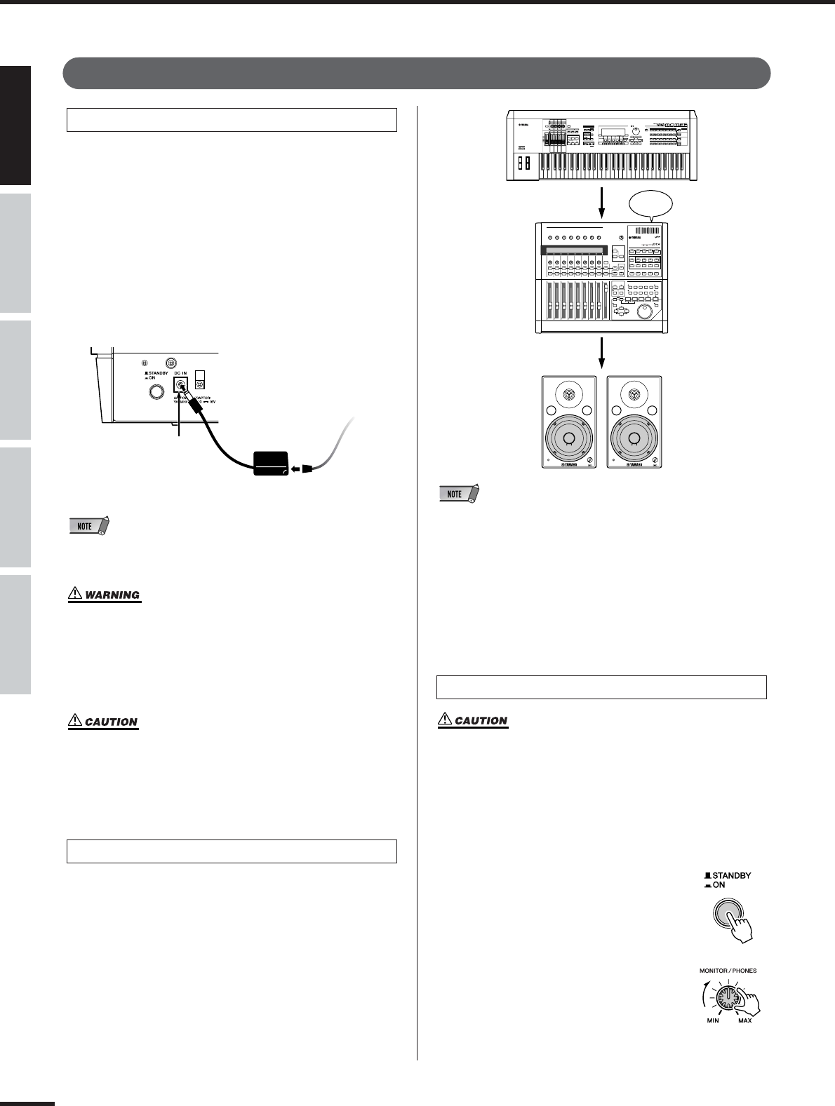
•Only use the voltage specified as correct for the instrument. The required
voltage is printed on the name plate of the instrument.
•Use the specified adaptor (PA-300 or an equivalent recommended by Yamaha)
only. Using the wrong adaptor can result in damage to the instrument or
overheating.
•Check the electric plug periodically and remove any dirt or dust which may
have accumulated on it.
•Do not place the AC adaptor cord near heat sources such as heaters or
radiators, and do not excessively bend or otherwise damage the cord, place
heavy objects on it, or place it in a position where anyone could walk on, trip
over, or roll anything over it.
•Do not open the instrument or attempt to disassemble the internal parts or
modify them in any way. The instrument contains no user-serviceable parts. If
it should appear to be malfunctioning, discontinue use immediately and have
it inspected by qualified Yamaha service personnel.
•Do not expose the instrument to rain, use it near water or in damp or wet
conditions, or place containers on it containing liquids which might spill into
any openings.
•Never insert or remove an electric plug with wet hands.
•Do not put burning items, such as candles, on the unit.
A burning item may fall over and cause a fire.
•If the AC adaptor cord or plug becomes frayed or damaged, or if there is a
sudden loss of sound during use of the instrument, or if any unusual smells or
smoke should appear to be caused by it, immediately turn off the power
switch, disconnect the adaptor plug from the outlet, and have the instrument
inspected by qualified Yamaha service personnel.
Power supply/AC power adaptor
Do not open
Water warning
Fire warning
If you notice any abnormality
(3)-7 1/2
01X Owner’s Manual
5
CAUTION
Always follow the basic precautions listed below to avoid the possibility of physical injury to you or others, or
damage to the instrument or other property. These precautions include, but are not limited to, the following:
•When removing the electric plug from the instrument or an outlet, always hold
the plug itself and not the cord.
•Unplug the AC power adaptor when not using the instrument, or during
electrical storms.
•Do not connect the instrument to an electrical outlet using a multiple-
connector. Doing so can result in lower sound quality, or possibly cause
overheating in the outlet.
•Do not expose the instrument to excessive dust or vibrations, or extreme cold
or heat (such as in direct sunlight, near a heater, or in a car during the day) to
prevent the possibility of panel disfiguration or damage to the internal
components.
•Do not use the instrument in the vicinity of a TV, radio, stereo equipment,
mobile phone, or other electric devices. Otherwise, the instrument, TV, or
radio may generate noise.
•Do not place the instrument in an unstable position where it might
accidentally fall over.
•Before moving the instrument, remove all connected adaptor and other cables.
•Do not place objects in front of the instrument’s air vent, since this may
prevent adequate ventilation of the internal components, and possibly result in
the instrument overheating.
•Before connecting the instrument to other electronic components, turn off the
power for all components. Before turning the power on or off for all
components, set all volume levels to minimum. Also, be sure to set the
volumes of all components at their minimum levels and gradually raise the
volume controls while playing the instrument to set the desired listening level.
•When cleaning the instrument, use a soft, dry cloth. Do not use paint thinners,
solvents, cleaning fluids, or chemical-impregnated wiping cloths.
•Do not insert a finger or hand in any gaps on the instrument.
•Never insert or drop paper, metallic, or other objects into the gaps on the
panel or keyboard. If this happens, turn off the power immediately and unplug
the power cord from the AC outlet. Then have the instrument inspected by
qualified Yamaha service personnel.
•Do not place vinyl, plastic or rubber objects on the instrument, since this
might discolor the panel or keyboard.
•Do not rest your weight on, or place heavy objects on the instrument, and do
not use excessive force on the buttons, switches or connectors.
•Do not operate the instrument for a long period of time at a high or
uncomfortable volume level, since this can cause permanent hearing loss. If
you experience any hearing loss or ringing in the ears, consult a physician.
Saving and backing up your data
•Any edited data (see page 36) that is left un-stored will be lost if you turn off
the power to the instrument. Save the data to the Library memory (see pages
50 and 54).
Saved data may be lost due to malfunction or incorrect operation. Save
important data to your computer.
Power supply/AC power adaptor
Location
Connections
Never attempt to turn off the power while data is being written to internal
memory (while a “Please keep power on...” message is shown). Turning the
power off in this state results in loss of all user data.
Maintenance
Handling caution
Saving data
Always turn the power off when the instrument is not in use.
Even when the power switch is in the “STANDBY” position, electricity is still flowing to the instrument at the minimum level. When you are not using the instrument for a
long time, make sure you unplug the AC power adaptor from the wall AC outlet.
If you feel any resistance when moving one of the faders, you should stop moving it. Never force a fader if it shows signs of resistance; doing so may
damage the device.
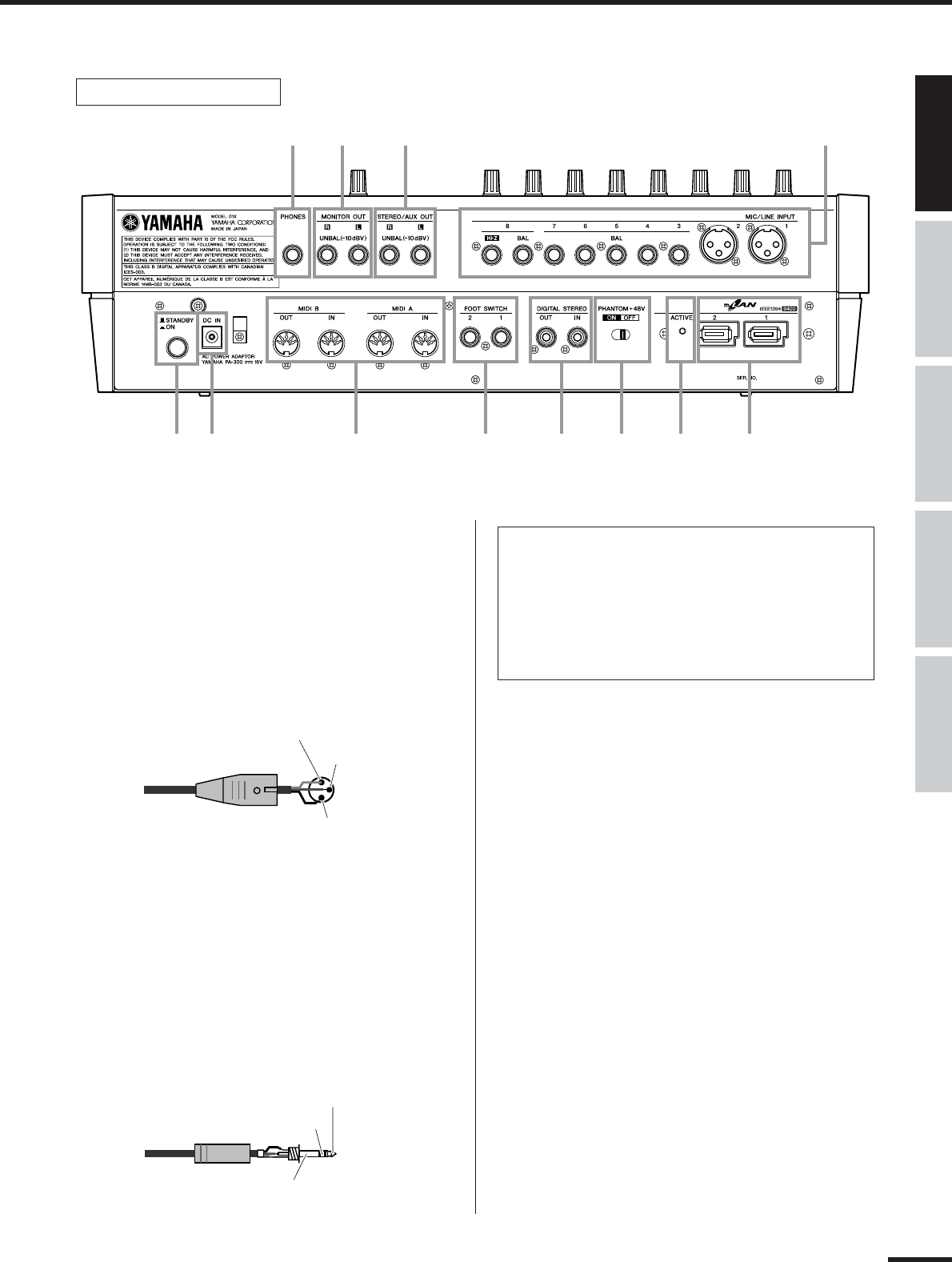
XLR-type connectors are wired as follows (IEC60268 standard): pin 1: ground, pin 2: hot (+), and pin 3: cold (-).
Yamaha cannot be held responsible for damage caused by improper use or modifications to the instrument, or data that is lost or destroyed.
(3)-7 2/2
6
01X Owner’s Manual
Introduction
Congratulations and thank you for purchasing the Yamaha 01X Digital Mixing Studio.
The 01X is a full-featured music production tool that effectively gives you three sophisti-
cated, comprehensive devices in one easy-to-use package — convenient remote control
over your computer-based DAW (digital audio workstation) via mLAN connection
(FireWire/i.Link/IEEE 1394), digital audio mixing with 24-bit/96kHz sound quality, and
full audio/MIDI interfacing with your computer environment via the mLAN connection.
With its wealth of built-in effects and advanced functions — not to mention its transparent,
seamless blend of software and hardware — the 01X is an excellent control console for
recording with an audio/MIDI sequencer, and is ideal for virtually any music creation/pro-
duction application.
In order to get the most out of your new 01X and its sophisticated functions, we suggest you
read through this manual thoroughly. Also keep it in a safe, convenient place so that you
can regularly refer to it when necessary.
Accessories (Check to see that you have everything listed here.)
AC Adaptor: PA-300 CD-ROM x 2 Installation Guide
Owner’s Manual mLAN cable
Quick Reference for Playback/Recording
User’s Card (containing the serial number for the included Plug-in software effects)
●Included CD-ROMs
These CD-ROMs contain special software for use with this instrument. They include the SQ01 (V2),
a full-featured audio/MIDI sequencer/mixer for comprehensive music production, Studio Manager,
which gives you comprehensive and intuitive mixer editing tools, and Multi Part Editor for MOTIF-
RACK editing the Mixing parameters of Songs and Patterns of the Yamaha MOTIF-RACK. Included
also are plug-in software effects that provide effect processing using the processing power of your
computer.
For details, see the separate Installation Guide or the online manuals included with the software.
01X Owner’s Manual
7
About This Manual
This manual consists of the following sections.
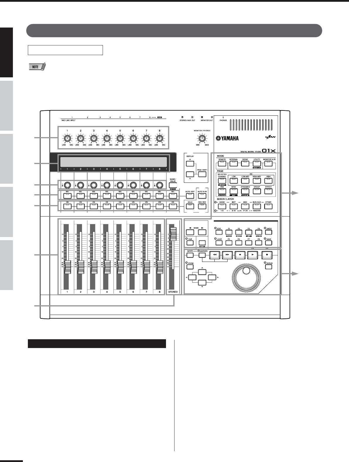
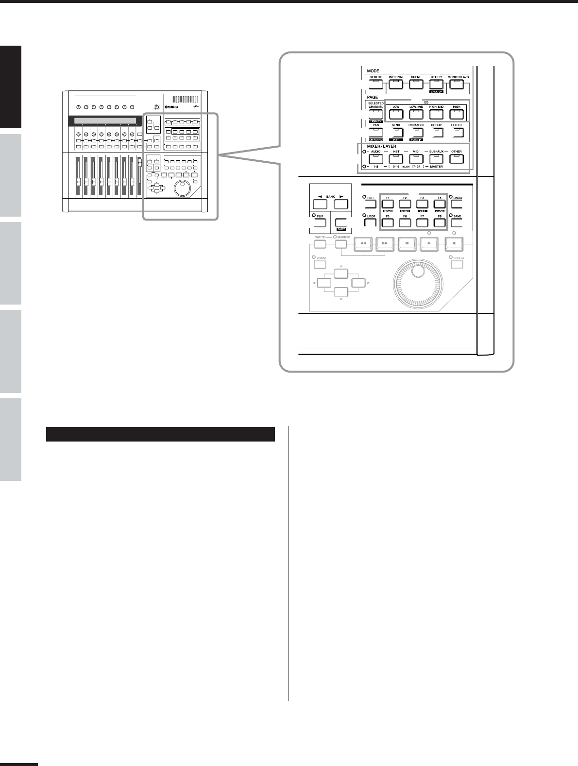
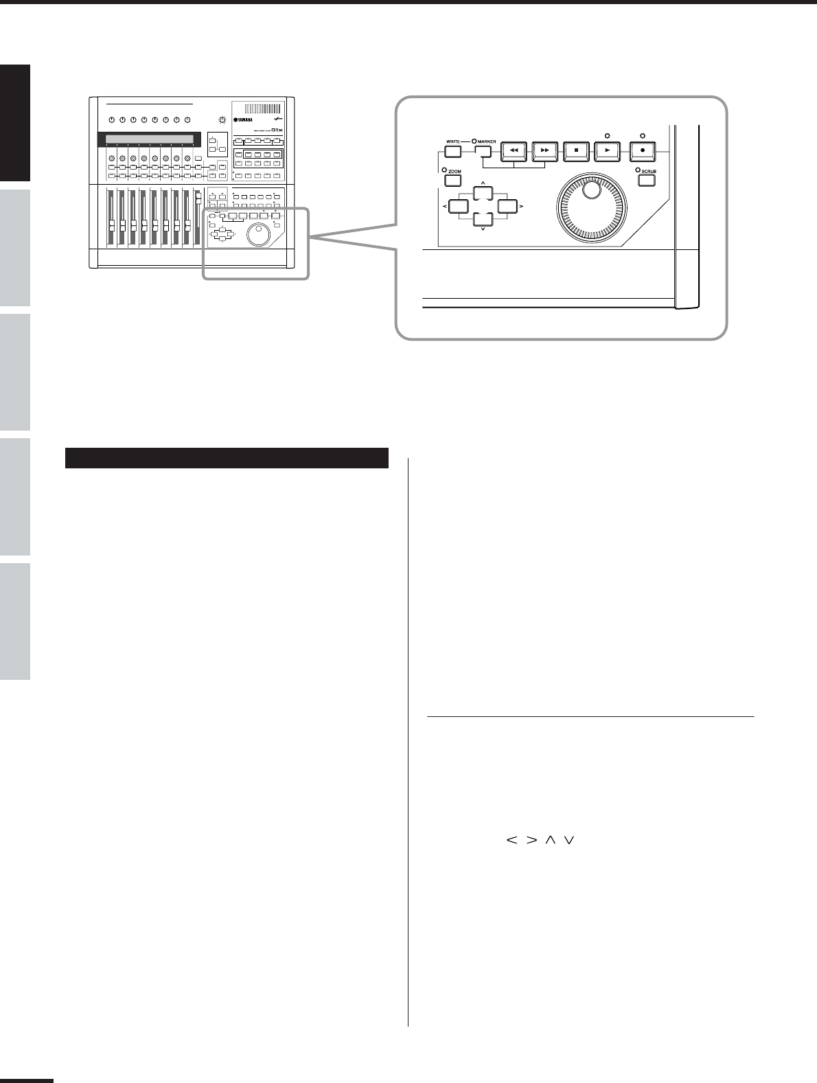
Before Using (page 14)
Use this section to find out about all of the buttons, controls and connectors of the 01X. It also explains how to set up the
instrument and connect external equipment.
Basics Section (page 25)
This section provides an overview of the main functions and features of the 01X and introduces you to the basic operating
conventions.
Getting Started (page 43)
This section explains how to use the basic functions of the 01X.
Reference (page 84)
This is the 01X encyclopedia. It explains all functions and parameters including the Remote functions.
Appendix (page 115)
This section contains various important lists such as the EQ Library list, Dynamics Library list, Effect Parameter list, and
MIDI Implementation Chart.
This section also contains detailed information on the 01X such as MIDI, Display Messages, Troubleshooting and Specifi-
cations.
Installation Guide (separate booklet)
Refer to this for instructions on installing the included software programs (on the CD-ROM) to your computer. This also
contains necessary system requirements for the 01X and supplementary software, mLAN setup, Remote Control Setup,
as well as information how to play the demo song, and computer software that can be controlled from the 01X.
•Copying of commercially available music sequence data and/or digital audio files for any purpose other than your own per-
sonal use, is strictly prohibited.
•This product incorporates and bundles computer programs and contents in which Yamaha owns copyrights or with respect to
which it has license to use others’ copyrights. Such copyrighted materials include, without limitation, all computer software,
styles files, MIDI files, WAVE data and sound recordings. Any unauthorized use of such programs and contents outside of per-
sonal use is not permitted under relevant laws. Any violation of copyright has legal consequences. DON’T MAKE, DISTRIB-
UTE OR USE ILLEGAL COPIES.
•The illustrations and screen displays as shown in this owner’s manual are for instructional purposes only, and may appear
somewhat different from those on your instrument.
•Most of the computer display examples in this owner’s manual are taken from the English version OS/software.
•The name “mLAN” and its logo () are trademarks of Yamaha Corporation.
•The company names and product names in this Owner’s Manual are the trademarks or registered trademarks of their respec-
tive companies.
8
01X Owner’s Manual
The 01X — What it is and what it can do
Powerful, multi-faceted digital mixer, computer audio recording interface,
and control surface—all in one
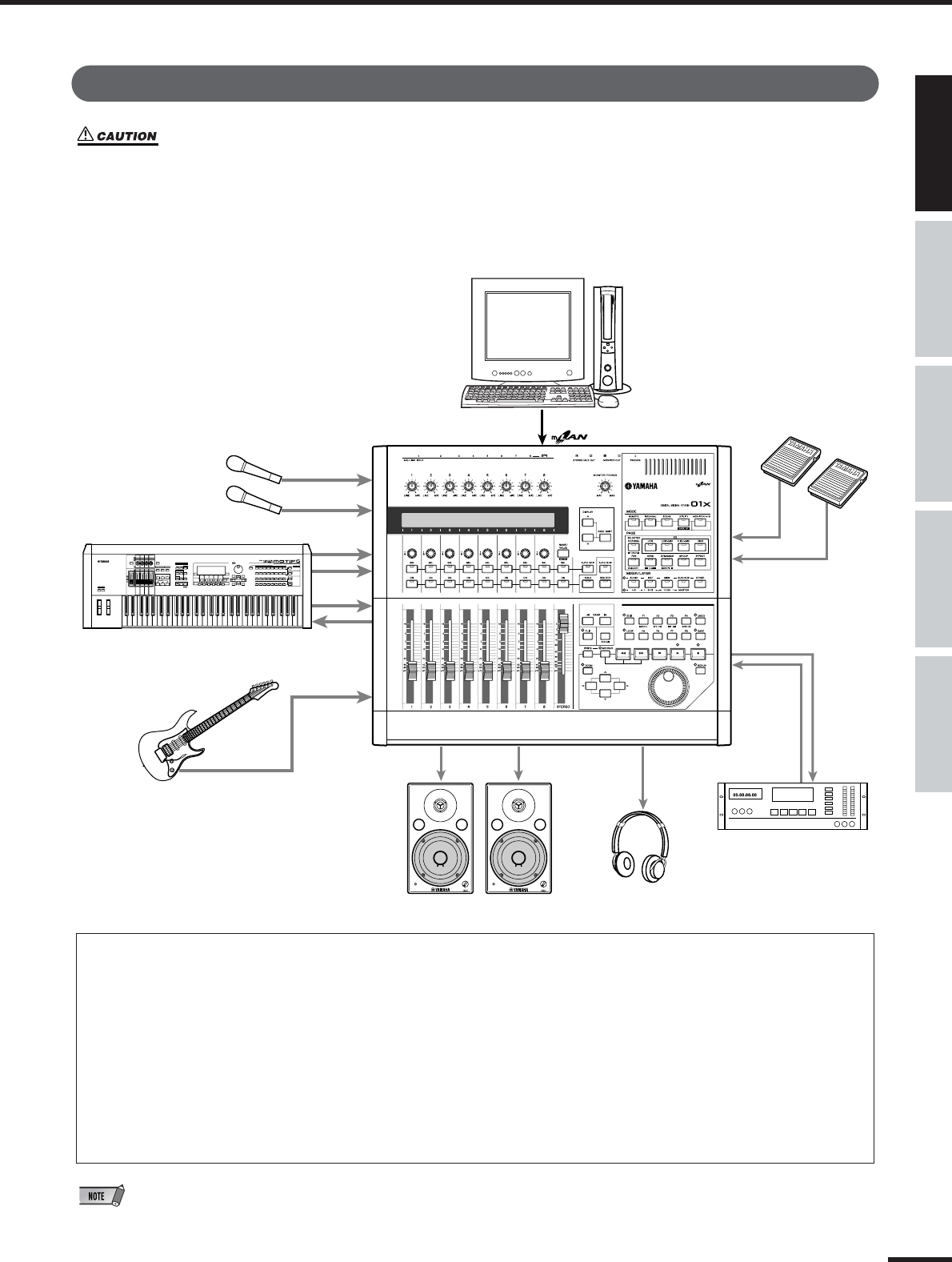
The 01X is actually several full-featured high-end digital devices in one compact, easy-to-use package. It serves as a flex-
ible 28-channel (maximum) digital mixer for recording in home and project studios, and even live applications. It’s also a
24-bit audio front-end for your computer, for high-resolution recording and playback of your sequencer/DAW tracks. It
gives you full transport and mixing control from the panel of most major sequencer/DAW software, and provides several
bundled software tools—including the virtual console Studio Manager, and the Channel Module—for getting the absolute
most out of your computer connection. Best of all, it can perform all of these tasks simultaneously, or at the flick of
switch. Let’s take a closer look.
Recording/mixdown console
As a mixer for recording purposes, the 01X is simple and compact, yet comprehensive in its mixing power. It has eight
hardware inputs, with two XLR-connector mic/line inputs and an alternate Hi-Z input on channel 8 for guitar or bass. With
an mLAN inputs/outputs, you can have up to 24 input channels (actually 28, including the stereo ins).
The fully digital 01X also features built-in compression/dynamics processing and EQ—independent for all channels—and
two effects blocks. What’s more, each processing section has its own set of Library presets, letting you instantly call up
the appropriate settings for your current application.
Highly portable, the versatile 01X is also ideal for mobile recording applications—even in multi-channel full band setups.
With the mLAN connection and the audio interface features (see below), all you need is a laptop computer and the 01X—
and you’ve got a full-featured recording studio you can take on the road.
Audio/MIDI interface for computer
The 01X also functions as a sophisticated high-quality audio front-end for your computer. Simply a connect a standard
IEEE 1394 (FireWire/i.Link) cable for high-speed data transfer and easy operation with IEEE 1394-capable (mLAN compat-
ible) computer. This gives you high-resolution 24-bit audio, with the sampling rate switchable between 44.1 kHz, 48kHz,
88.2kHz (Macintosh only) and 96kHz.
The 01X is also a multi-port MIDI interface for your computer, with two sets of MIDI terminals on the rear panel. The
mLAN interface also handles MIDI, giving you five independent MIDI ports (page 95).
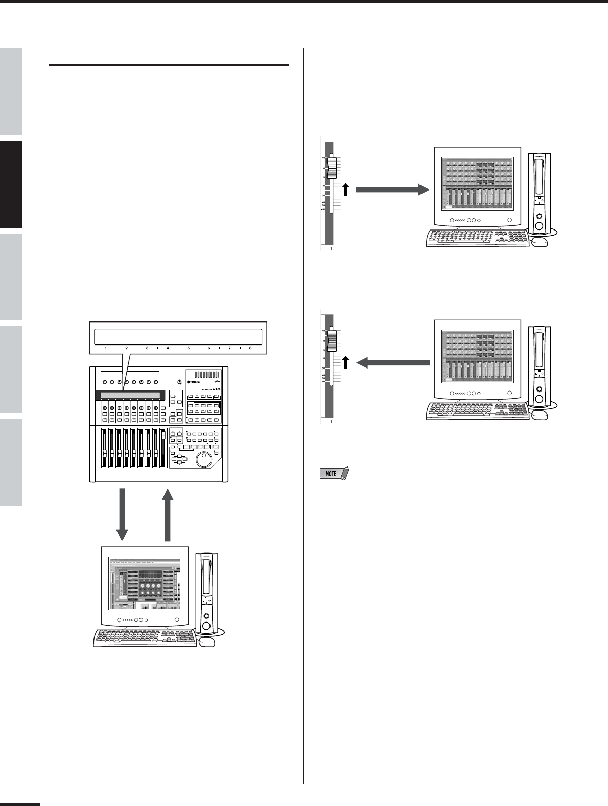
Remote control surface for computer sequencers and digital audio workstations (DAWs)
More than just a conventional mixer, the 01X is also a convenient, comprehensive control surface for your sequencer or
DAW application. It features tape recorder style transport controls, window navigation buttons, and allows you to use the
faders, knobs and channel buttons for mixing your sequencer tracks in real time. Which means you have full automation
control over your mix—and can even change and automate EQ and effect settings for each track. Most major DAW appli-
cations and MIDI/audio sequencers are supported, including Cubase SX/SL, Nuendo, Logic, SONAR, and Digital Per-
former.
The 01X is a perfect hybrid of the analog and digital—you get the benefits of clean digital sound, yet you still have physi-
cal knobs, sliders and switches to touch, giving you hands-on control. You’ll find these features useful as creative com-
posing and arranging tools as well—for example, in programming mutes and fades on the fly as the tracks play back.
01X Owner’s Manual
9
Powerful software applications
Included with your 01X are a variety of useful plug-ins and software programs to help you get the most out of the mixer
and your computer music system.
• 01X Channel Module
This plug-in software provides at-a-glance control over all Dynamics and EQ processing for an 01X channel. It lets
you call up Dynamics and EQ Library presets from the computer, tweak them using the intuitive controls and compre-
hensive displays, save your custom settings, and import/export settings to and from the connected 01X. In this way,
you can set and use the Channel Module to process your sequencer tracks on the computer, and export the settings
to the 01X—using the hardware processing on the mixer to save processing power on your computer.
• Plug-in Effects
Use these powerful tools in your sequencer or DAW for recording, processing, editing and mastering:
Vocal Rack— Multi-effect processor perfect for recording vocals
Pitch Fix— Comprehensive, “fix-it-in-mix” pitch editing for vocals
Final Master— Mastering effect w/multi-band compressor, limiter, and soft-clip feature
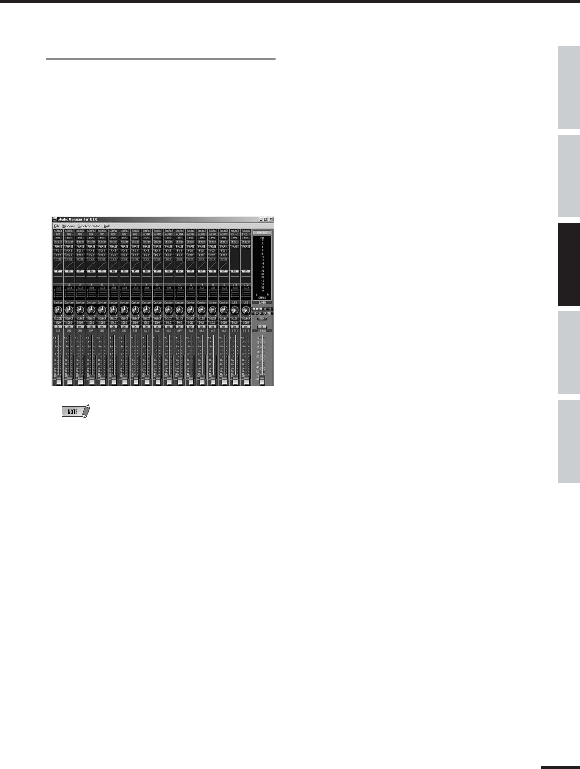
• Studio Manager for 01X
This stand-alone virtual mixer software is a convenient direct link between the 01X and your computer. Utilizing the
mLAN connection, it provides virtual channel strips for all 01X channels— with faders, pan controls and real-time
metering—and lets you see all your Dynamics and EQ edits on the monitor.
• SQ01 V2 (Windows only)
This is the latest version of Yamaha’s powerful audio/MIDI sequencer, featuring a new Audio Mixer window. The
SQ01 V2 lets you easily record, edit and play back your own songs on computer, and provides a seamless environ-
ment for the included Plug-in software (as well as third-party plug-ins).
• TWE Wave Editor (Windows only)
This audio editing software is comprehensive, yet simple and easy to use—giving you the tools to change, enhance
and transform your audio recordings.
• Multi Part Editor for MOTIF-RACK (Windows only)
This convenient software allows you to edit the Mixing parameters (including effects) of the MOTIF-RACK from your
computer, when using the MOTIF-RACK as a multi-timbral tone generator.
10
01X Owner’s Manual
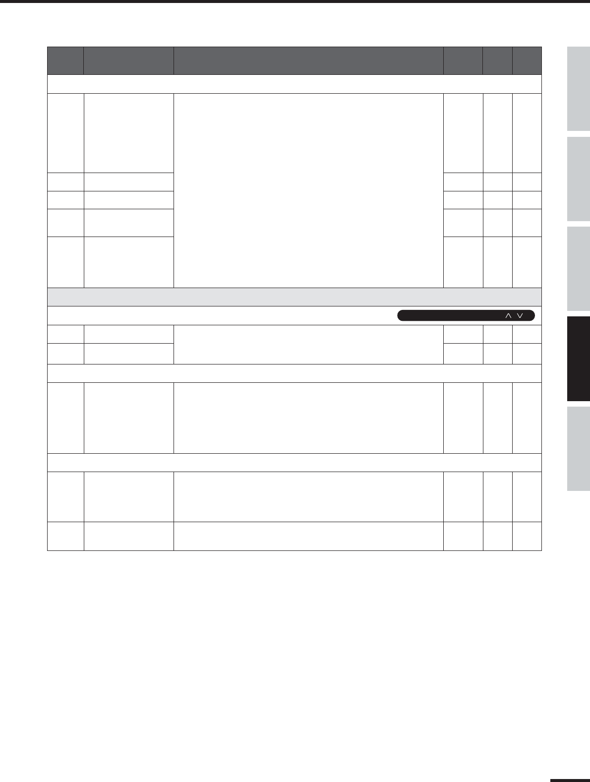
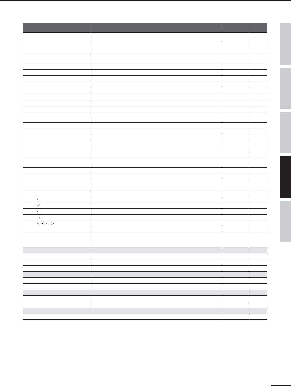
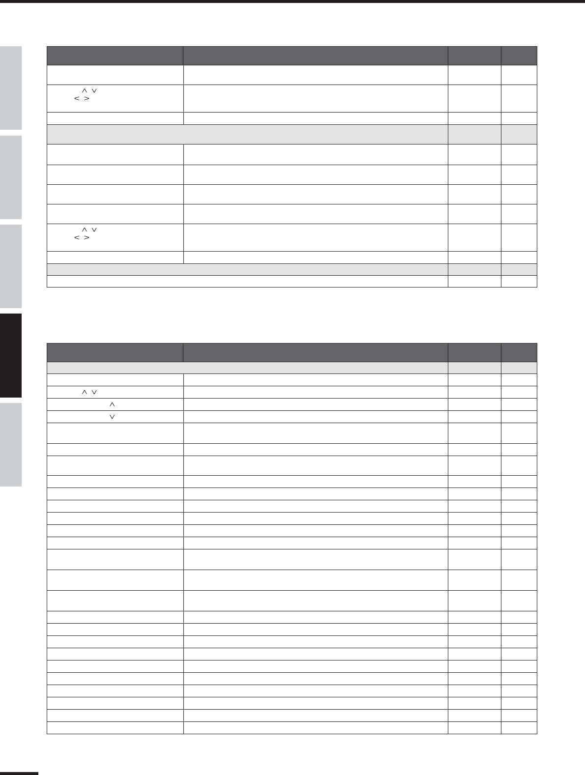
Application Index
This convenient, easy-to use index is divided into general categories to help you when you want to find informa-
tion on a specific topic or function. For information on the electronic owner’s manuals (PDF), refer to the sepa-
rate Installation Guide.
■Installation/Normal Settings
●
Uninstall (removing the installed application) .......................................................................................................................................(Installation Guide)
Selecting the IEEE 1394 card (when multiple cards are installed)..................................................................mLAN Driver Setup (Installation Guide)
●
Listening to Demo songs..........................................................................................................................................................................(Installation Guide)
Switches between automatic/manual setting of mLAN wordclock. .....................................................................................W.CLK SELECT (page 92)
●
Setting the sampling frequency (frequency of the wordclock) (when mLAN is used).........................................Auto Connector (Installation Guide)
■Accessory software and mLAN related settings.
●
Determining the number of mLAN audio transmission/reception channels.......................................................... Auto Connector (Installation Guide)
●
Setting the sampling frequency (frequency of the wordclock) (when mLAN is used).........................................Auto Connector (Installation Guide)
●
Determining the speed at which settings are
changed when new wordclock is received....................................................Auto Connector ➝ Setup (mLAN Transition Speed) (Installation Guide)
●
Quits/enables mLAN network in Windows.........................................................................................Task bar ➝ mLAN icon ➝ OFF (Installation Guide)
●
Determining the latency (how quickly the data is processed).
•Basic settings made in mLAN Driver...............................................................................................mLAN Driver Setup ➝ Latency (Installation Guide)
•Settings made in relevant application.............................................................ASIO mLAN Control Panel ➝ Preferred Buffer Size (Installation Guide)
●
Determining the audio driver (ASIO/WDM) used with mLAN............................................................mLAN Driver Setup ➝ Mode (Installation Guide)
●
Checking the reception condition of mLAN (from 01X to computer)............................mLAN Driver Setup ➝ Status/Information (Installation Guide)
●
Using the same 01X EQ and Dynamics effects
from the computer, using the computer’s processing power...........................01X Channel Module (01X Channel Module Owner’s Manual; PDF)
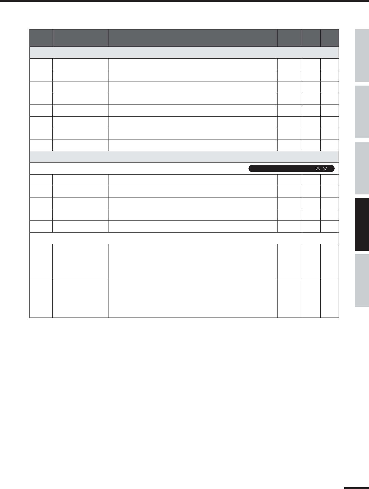
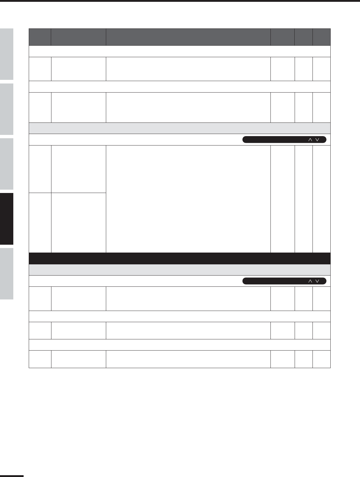
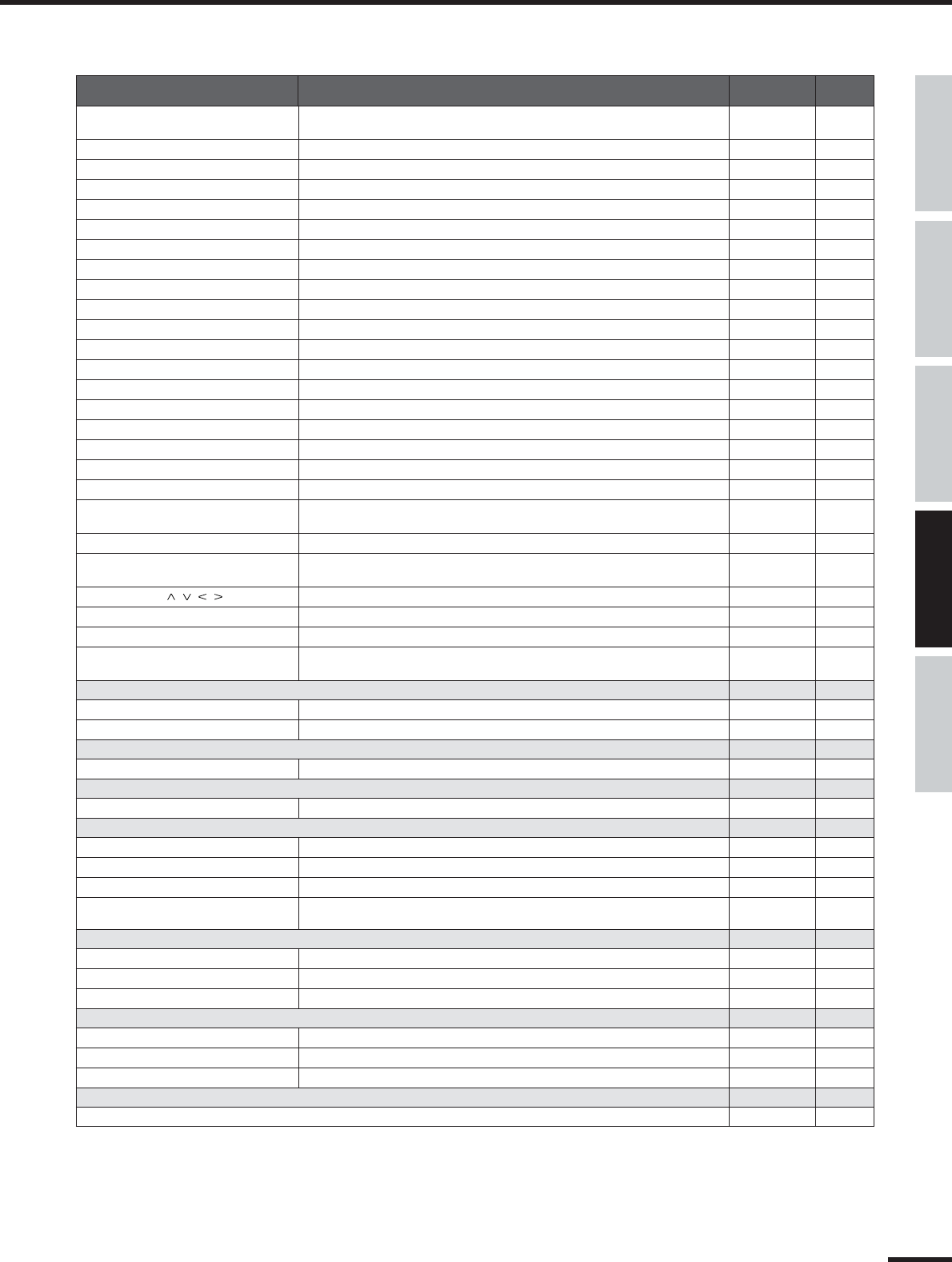
■Frequent settings for Recording/Playing back
●
Determining the number of mLAN audio transmission/reception channels.......................................................... Auto Connector (Installation Guide)
●
Setting the sampling rate (wordclock) when using mLAN. ..................................................................................... Auto Connector (Installation Guide)
●
Determining the latency (how quickly the data is processed).
•Basic settings made in mLAN Driver...............................................................................................mLAN Driver Setup ➝ Latency (Installation Guide)
•Settings made in relevant application.............................................................ASIO mLAN Control Panel ➝ Preferred Buffer Size (Installation Guide)
●
Determining the audio driver (ASIO/WDM) used with mLAN............................................................mLAN Driver Setup ➝ Mode (Installation Guide)
●
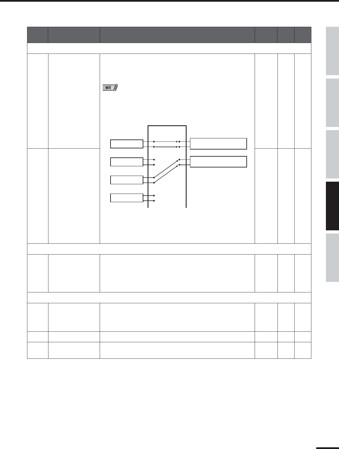
Monitoring/outputting the DAW (digital audio workstation) sound from the 01X.
•Outputting the sound via internal mixer (input module) of the 01X .............................................................................................MONITOR (page 96)
•Outputting the sound separate from the internal mixer of the 01X (using the monitor input)..................................................MONITOR (page 96)
●
Recording individual input channels of the 01X to the DAW. ...................................................OUTPUT PATCH (mLAN OUT CHANNEL) (page 90)
●
Recording a mix of the input channels of the 01X to the DAW. ...............................................OUTPUT PATCH (mLAN OUT CHANNEL) (page 90)
●
Recording channels of the 01X dry and unprocessed, or recording with EQ and Dynamics processing....... DIRECT OUT POSITION (page 91)
●
Connecting the DAW or MIDI sequencer by MIDI................................................................................................................................................(page 95)
■Adjusting the recording level
●
Adjusting the gain of the analog input...........................................................................................................................................Gain knob (pages 16, 43)
●
Checking the input signal for clipping............................................................Switching the meter display. (INPUT METER POINT=PRE EQ) (page 46)
●
Controlling the volume digitally (with the 01X faders).............................................................................................. DIRECT OUT POSITION (page 91)
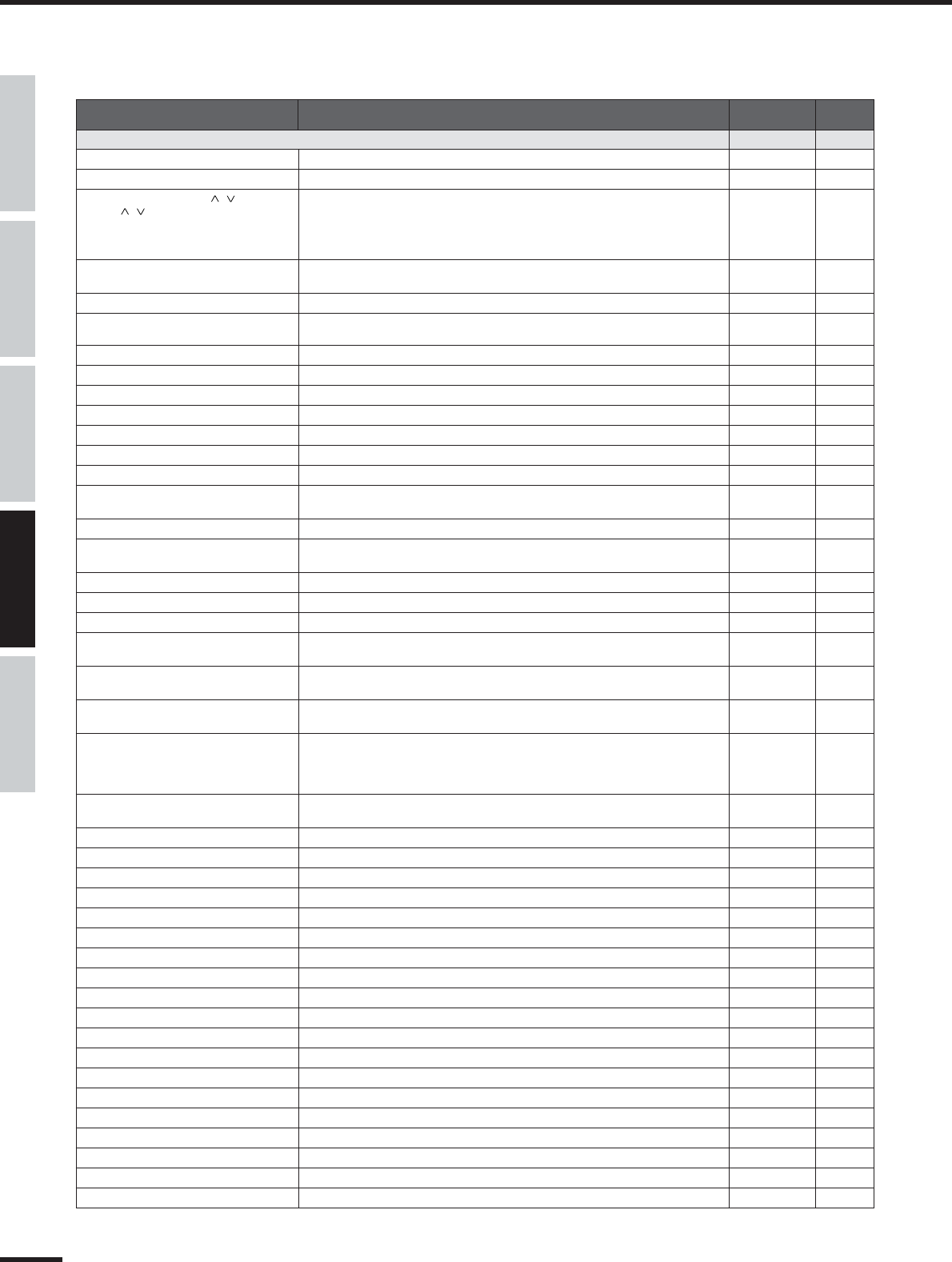
■Editing the song/data from the computer/DAW
●
Editing the pitch of the vocal..............................................................................................................................Pitch Fix (Pitch Fix Owner’s Manual; PDF)
●
Controlling the Pitch Fix plug-in effect via MIDI data from the host application.
(Using MIDI to change the pitch of a vocal or to switch scenes.)...........................................................................(Pitch Fix Owner’s Manual; PDF)
●
Using multi-effects in vocal recording. .....................................................................................................Vocal Rack (Vocal Rack Owner’s Manual; PDF)
●
Using multi-effects in mastering............................................................................................................Final Master (Final Master Owner’s Manual; PDF)
●
Editing and viewing the 01X settings on the computer...........................................................Studio Manager (Studio Manager Owner’s Manual; PDF)
●
Saving the 01X’s settings to a computer.................................................................................Studio Manager (Studio Manager Owner’s Manual; PDF)
●
Transferring settings between the 01X Channel Module and the Studio Manager.
Backing up system data......................................................................................................................................BACKUP ([SHIFT]+[UTILITY] (page 86)
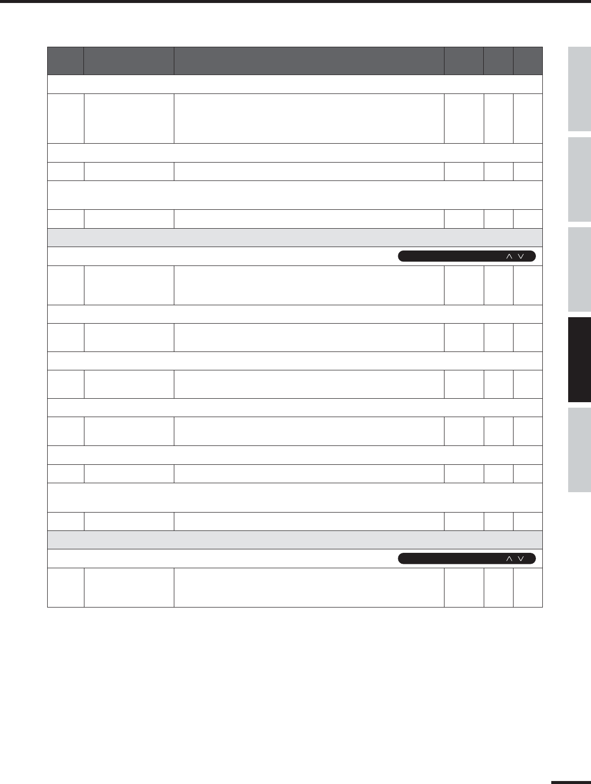
●
Saving/recalling/deleting groups of programmed settings (Library)................................................................................................LIBRARY (page 36)
●
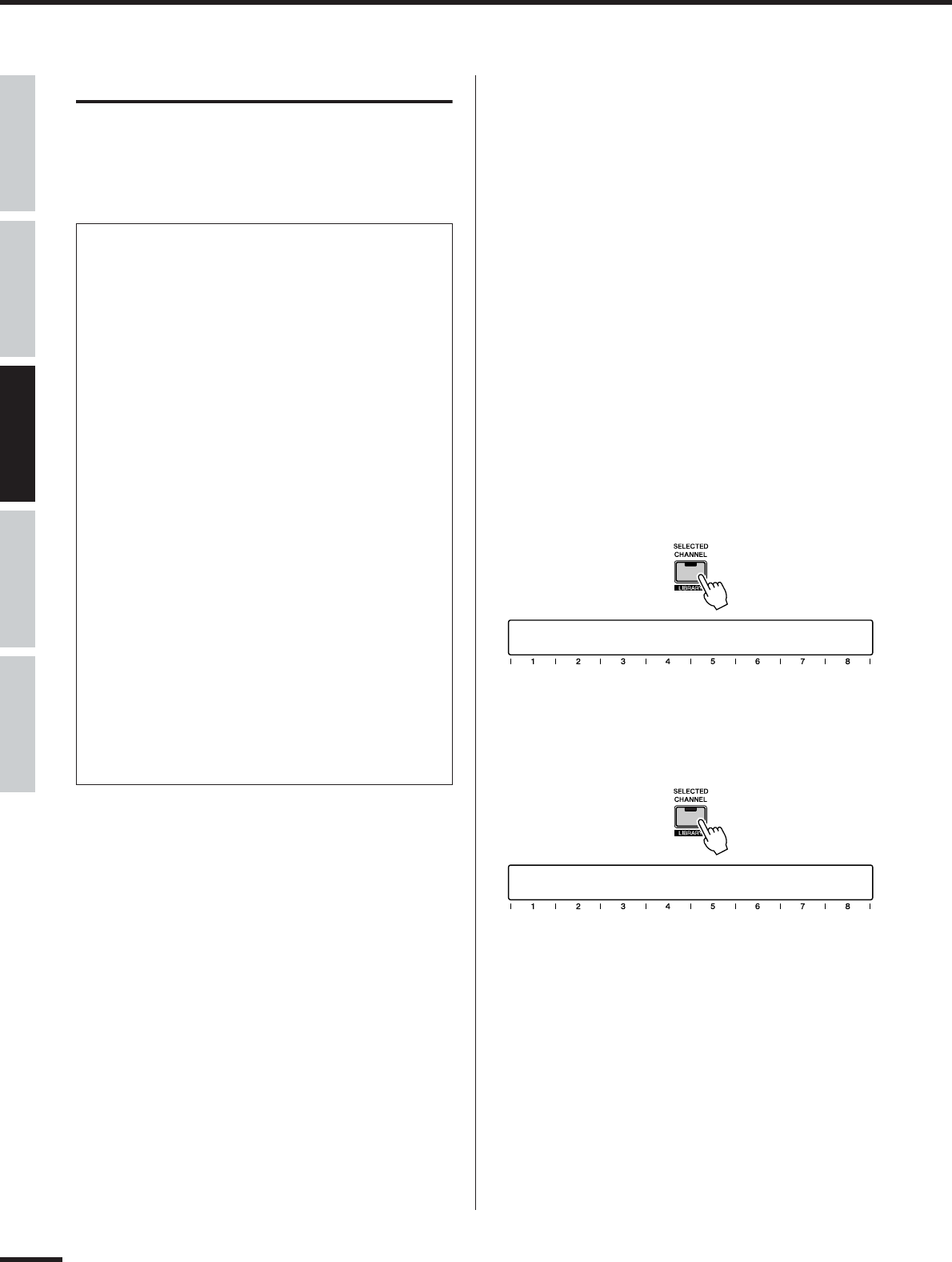
Using the channel Library. ........................................................................................................................[SHIFT] + [SELECTED CHANNEL] (page 103)
●
Saving the 01X’s settings to a computer.................................................................................Studio Manager (Studio Manager Owner’s Manual; PDF)
■Protecting data from accidental loss
●
Setting a Scene so that data cannot be deleted/edited (Scene Protect). ......................................................................................PROTECT (page 86)
●
Specifying a certain channel to not be affected by recalling a Scene (Recall Safe)...........................................................RECALL SAFE (page 86)
●
Specifying the stereo channel to not be affected by recalling a Scene (Recall Safe).........................................................RECALL SAFE (page 86)
■Entering data
●
Entering characters (Library name settings).........................................................................................................................................Title Edit (page 41)
■Resetting parameters (Initializing)
●
Resetting the 01X to its default settings (Factory Set).....................................................................................................................Factory Set (page 42)
●
Initializing Scene parameters...................................................................................................................Scene Library ➝ recalling Library #00 (page 85)
Switches between automatic/manual setting of mLAN wordclock. .....................................................................................W.CLK SELECT (page 92)
●
Setting the sampling rate (wordclock).
•When the 01X is the master...............................................................................................mLAN AUTO W.CLK (mLAN AUTO Wordclock) (page 92)
•When using mLAN...................................................................................................................................................... Auto Connector (Installation Guide)
■Remote Control
●
Selecting the DAW/sequencer to be remotely controlled...................................................................................................REMOTE SELECT (page 87)
●
Emulating touch-sensitive fader control.
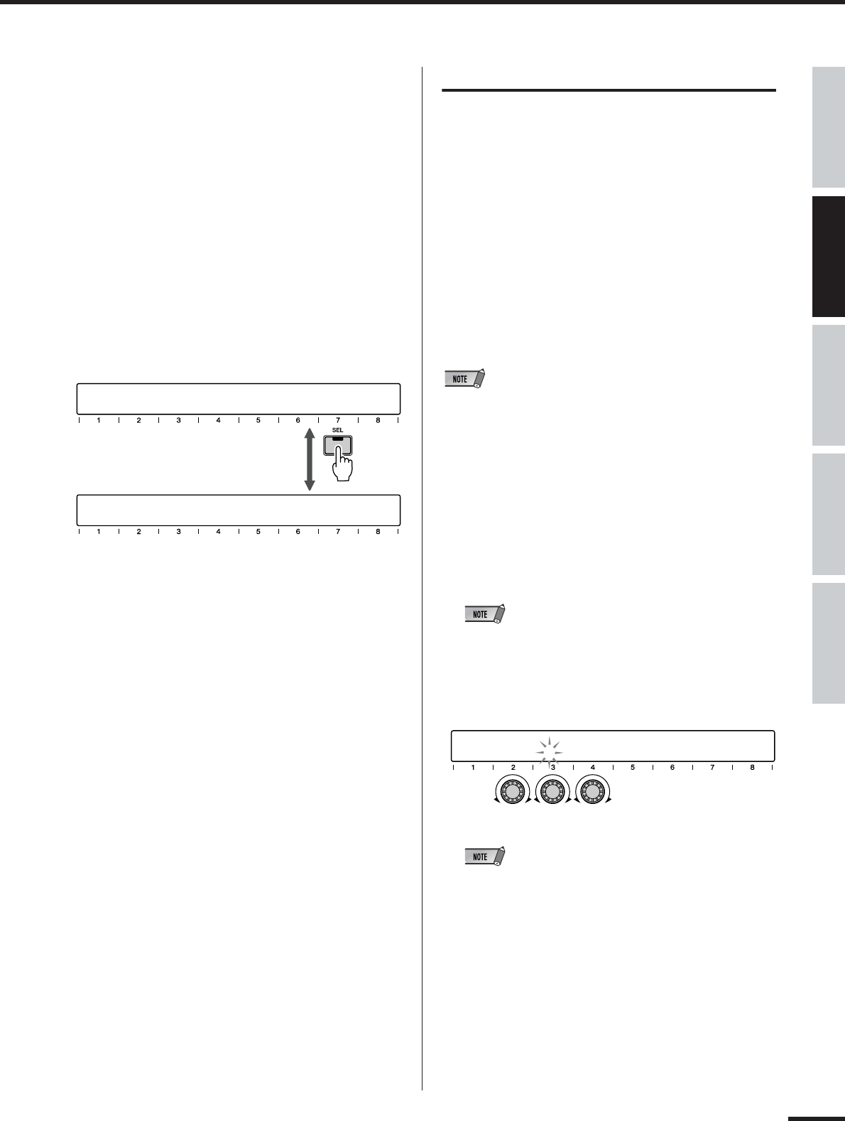
•Continuing automation recording even after fader movement is stopped...................REMOTE AUTOMATION SETUP/[SEL] (pages 15, 17, 88)
•Starting automation recording before fader is moved......................................................................................[AUTO EDIT]/[SEL] (pages 15, 17, 88)
●
Setting the time that the 01X “waits” before turning off fader recording.
(Can also be set to no “time-out”, or constant recording.).....................................................................REMOTE AUTOMATION SETUP (page 88)
●
Remote control of the Multi-Part Editor, by using the [SHIFT] + [REMOTE] buttons. .........................................[SHIFT]+[REMOTE] (pages 37, 87)
●
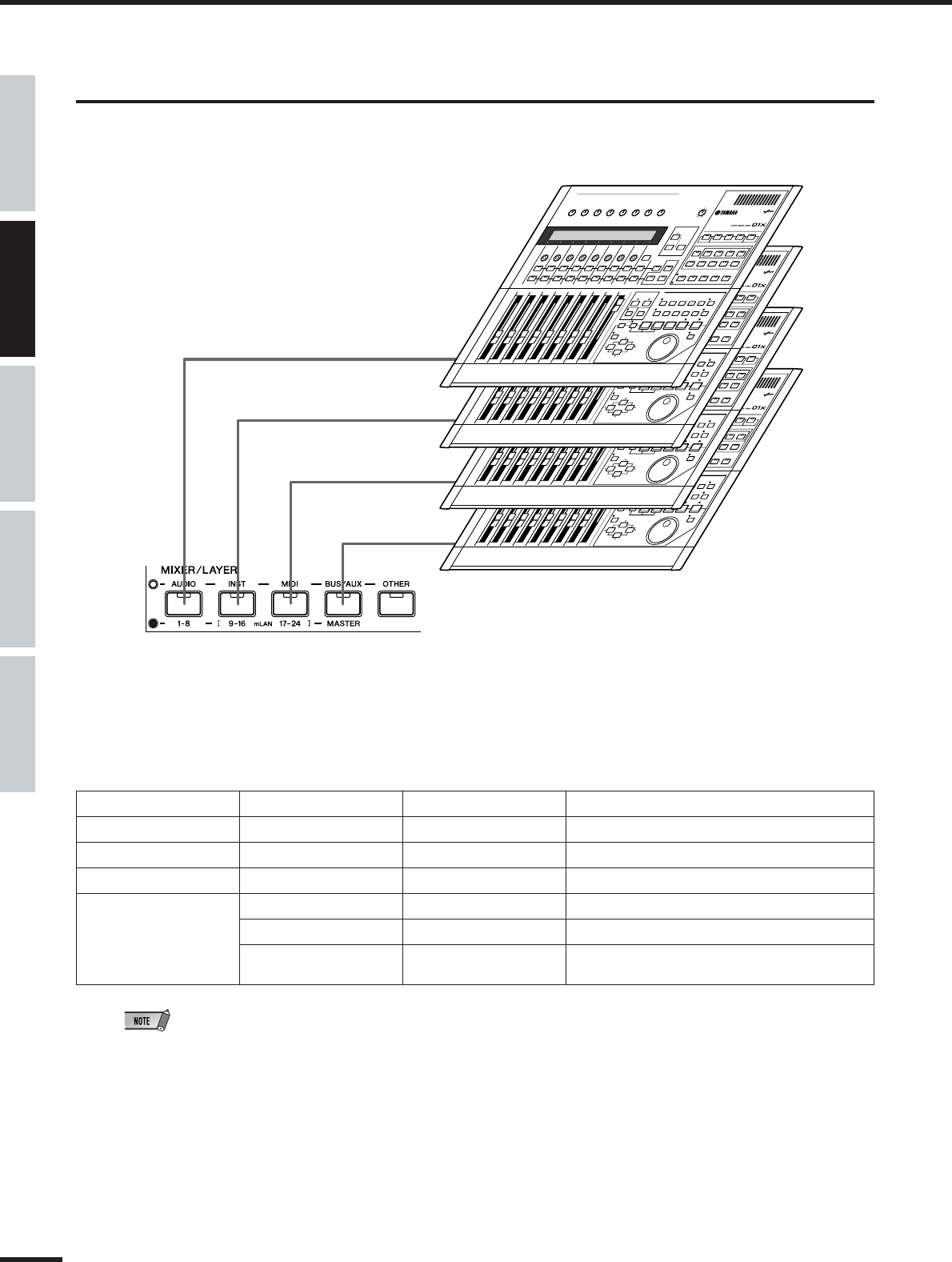
Switching between remote control and internal mixer operation. .....................................................................................Modes (Mode List) (page 37)
■Miscellaneous operations
●
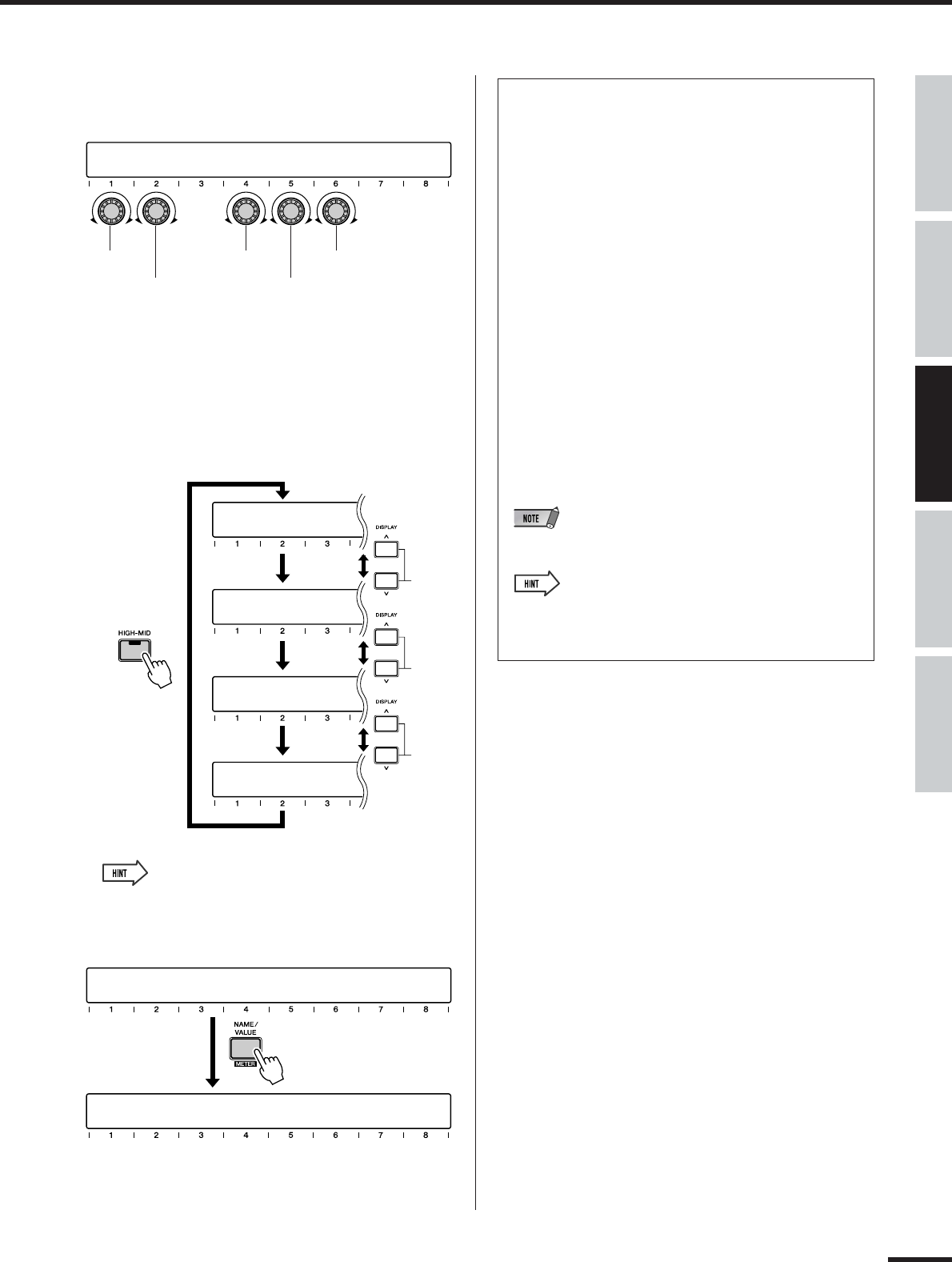
Speeding up adjustment of numeric values when using the knobs. ..........................................................................[SHIFT]+Channel knob (page 17)
●
Switching (exchanging) the functions of the channel faders and knobs...............................................................................................[FLIP] (page 19)
●
Assigning the function of the channel knob to the fader as well............................................................................................[SHIFT]+[FLIP] (page 19)
●
Assigning control of the fader operation and
settings to odd/even channel pairs (setting one channel controls the other). ...........................................................................CH PAIR (page 102)
●
Assigning fader operations in groups.......................................................................................................................................FADER GROUP (page 101)
●
Assigning [ON] button operations in groups. ............................................................................................................................MUTE GROUP (page 101)
●
Switching between soloing of multiple channels or a single selected channel. ......................................................................SOLO MODE (page 96)
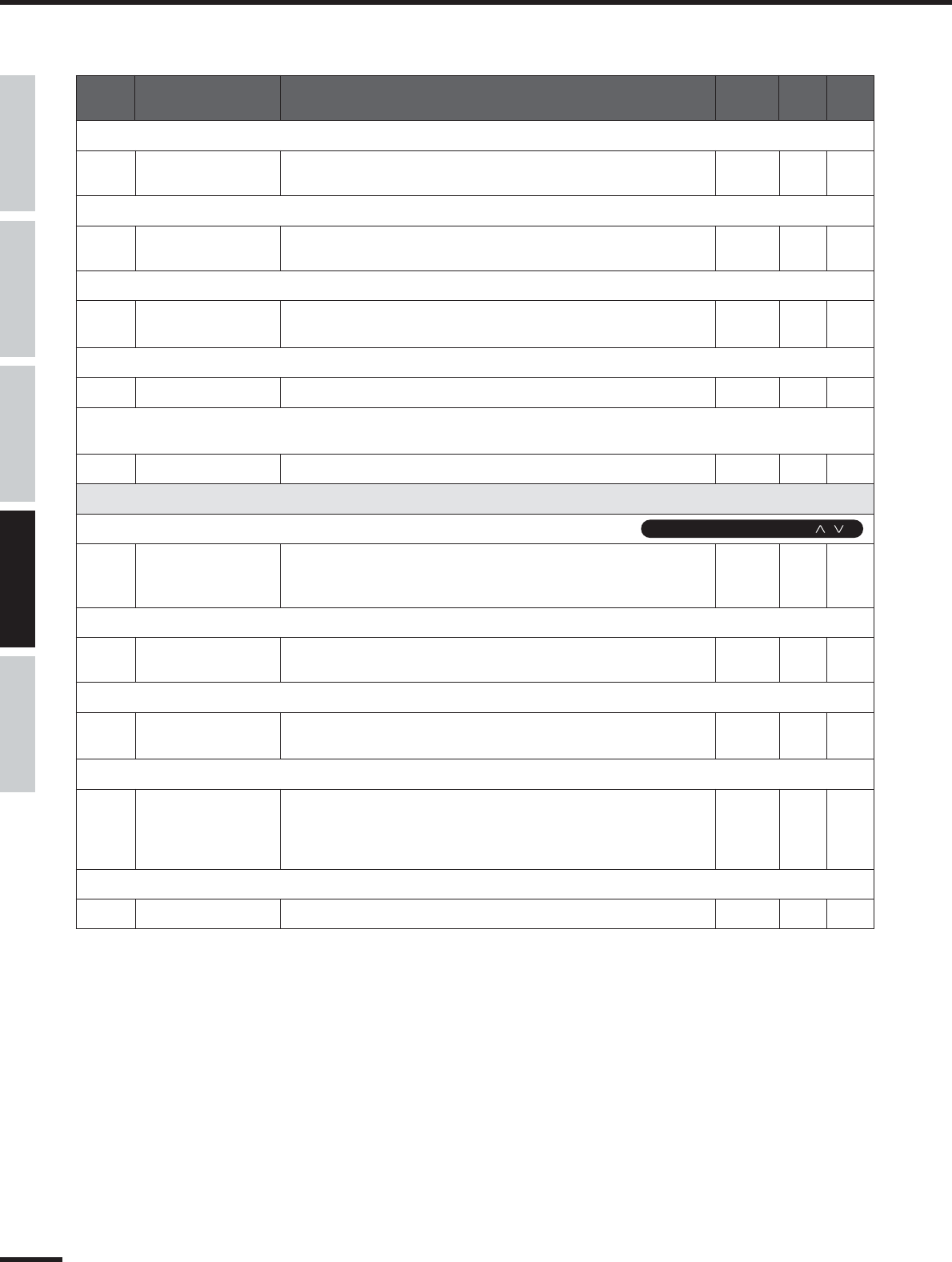
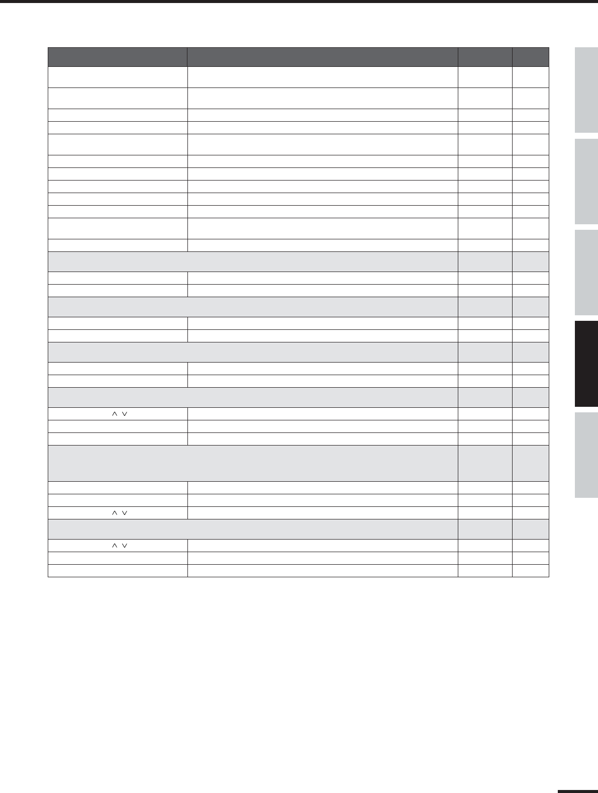
■Display
●
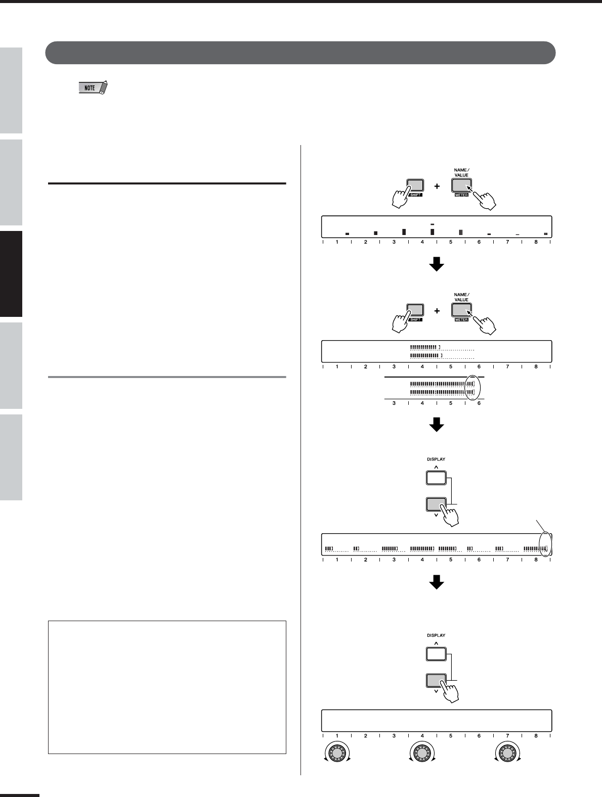
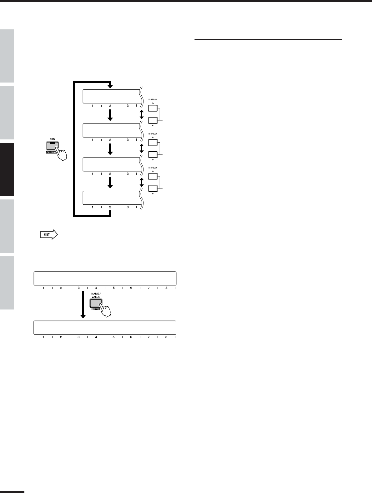
Toggling among the different display indications for the meter and parameter/value displays........................[SHIFT]+[NAME/VALUE] (page 46)
●
Determining the time the parameter value remains displayed (when NAME/VALUE is set to “NAME”)..................PARAM DISP TIME (page 95)
●
Determining whether the channel level is shown or not when a fader is moved........................................................FADER LEVEL DISP (page 95)
●
Switching the display indication between channels/parameters/values and only values. ................................................[NAME/VALUE] (page 17)
●
Switching between level meter display of the pre-fader signal or post-fader................................................................................................... (page 46)
●
Determining whether a confirmation prompt appears or not for store/recall operations...................STORE/RECALL CONFIRMATION (page 95)
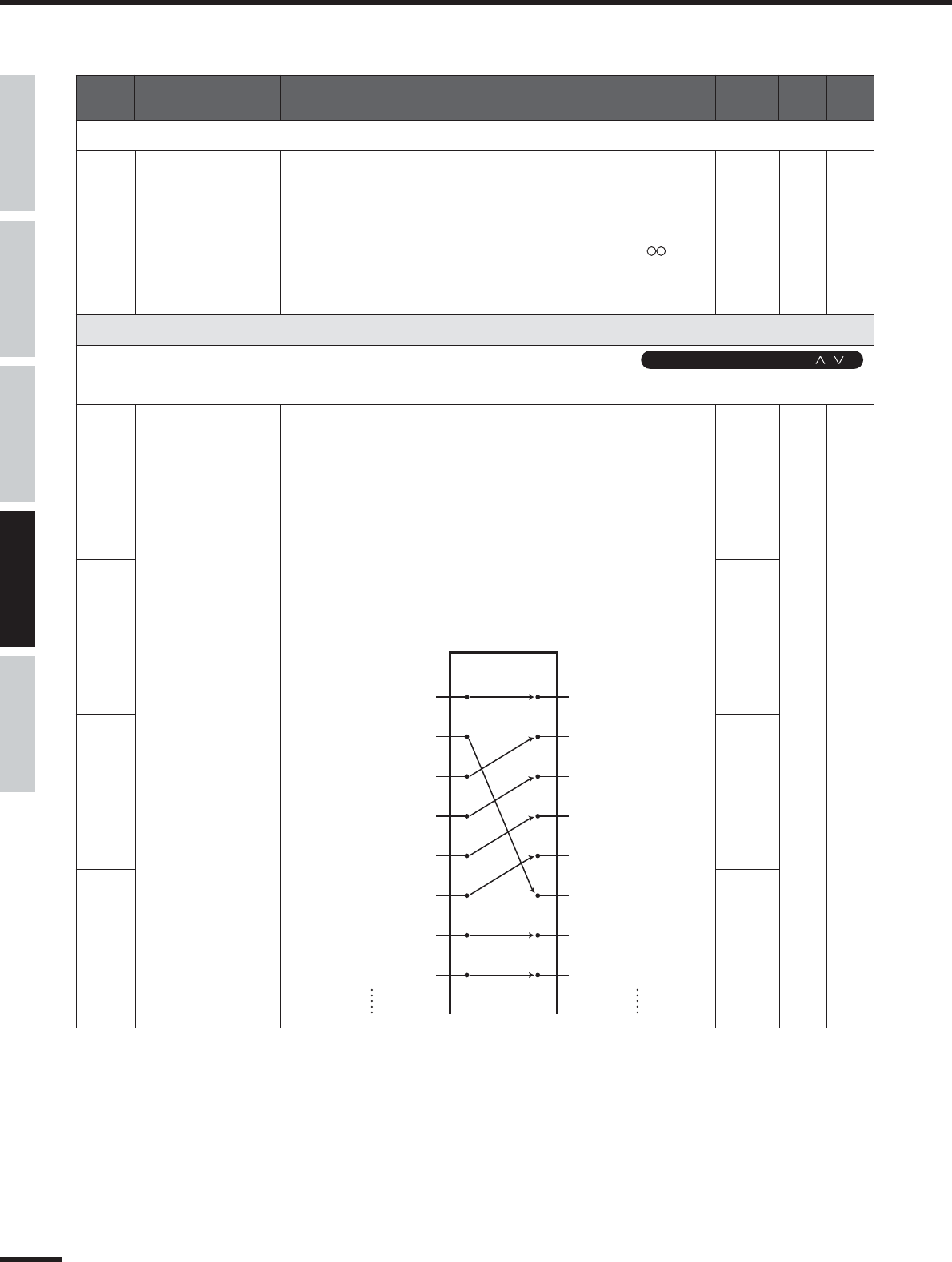
■Input
●
Assigning the input signals (from MIC/LINE INPUT,
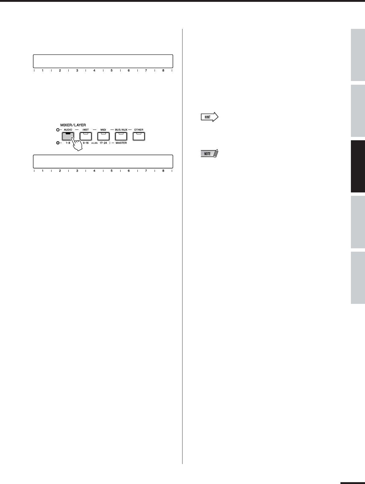
DIGITAL STEREO IN terminals) to the input channels on the mixer.....................................................................INPUT PATCH (IN1-8) (page 88)
●
Assigning the input signals (from MIC/LINE INPUT,
DIGITAL STEREO IN terminals and Effects 1/2) to the stereo input channels on the mixer.............................INPUT PATCH (ST1/2) (page 89)
●
Switching the phase setting of an input channel.....................................................................................................................................PHASE (page 99)
12
01X Owner’s Manual
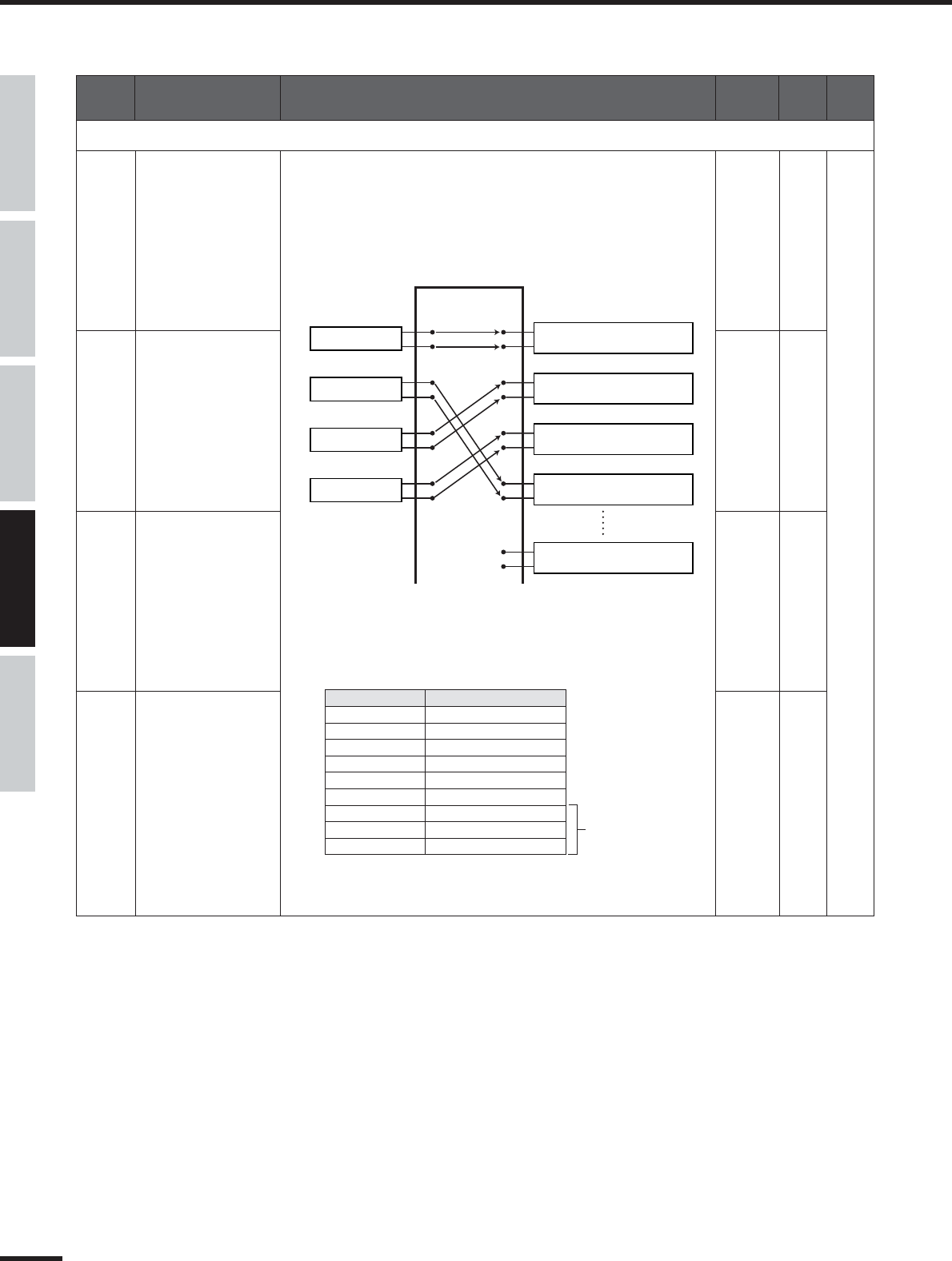
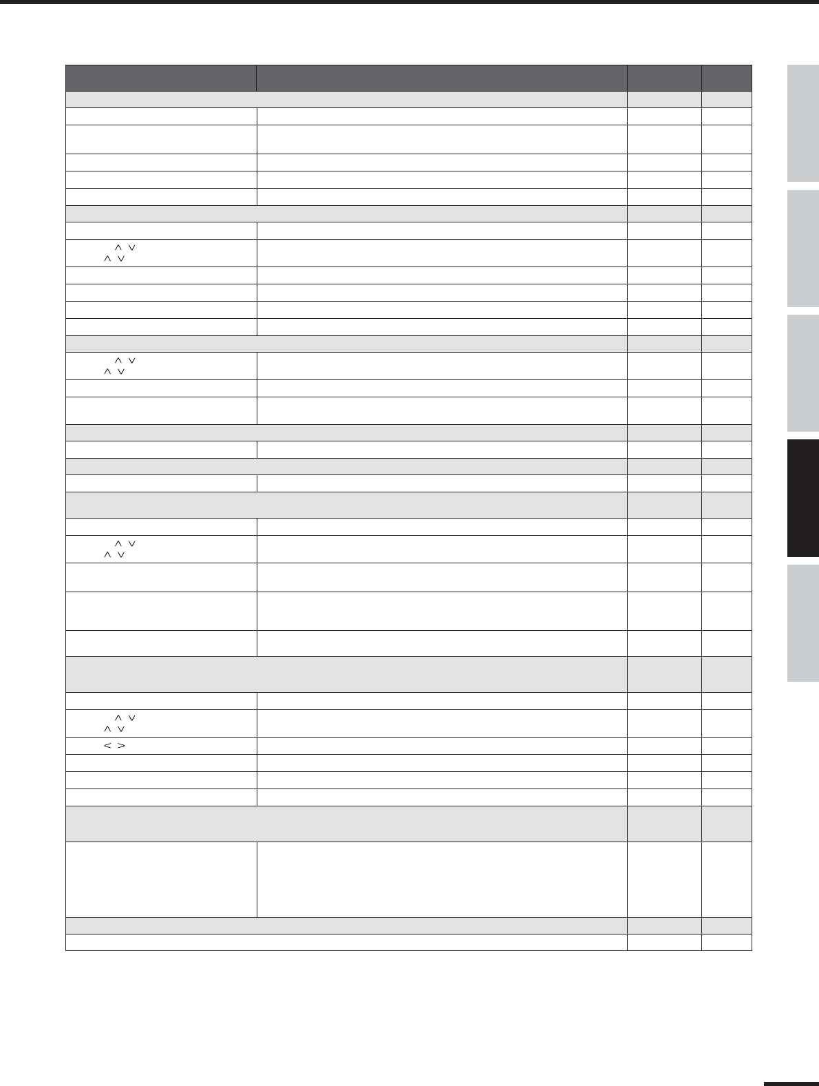
■Output
●
Outputting only the DAW’s stereo output to Monitor Out or headphones..............................................................................MONITOR (pages 37, 96)
●
Outputting only the stereo output of the 01X to Monitor Out or headphones.......................................................................MONITOR (pages 37, 96)
●
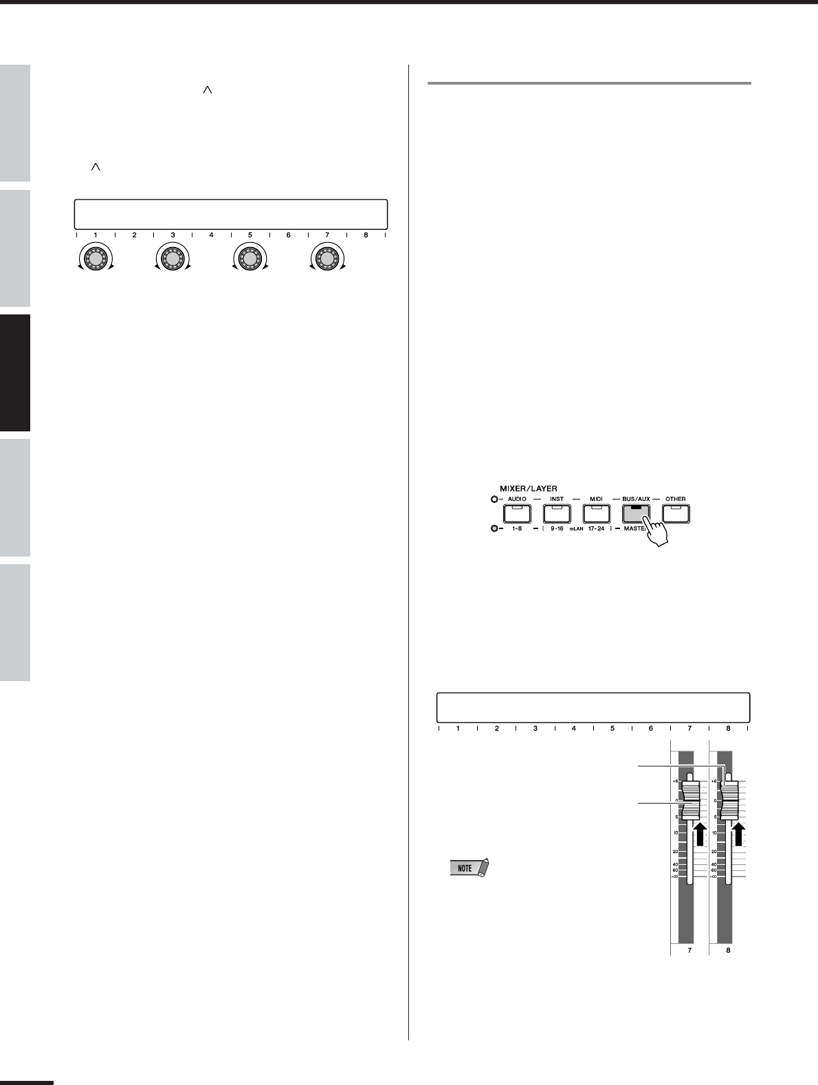
Assigning the stereo bus, Rec bus and Aux bus signals to the desired mLAN outputs.......OUTPUT PATCH (mLAN OUT CHANNEL) (page 90)
●
Selecting which signals (stereo bus, Rec bus, Aux bus 1/2 or Aux bus 3/4)
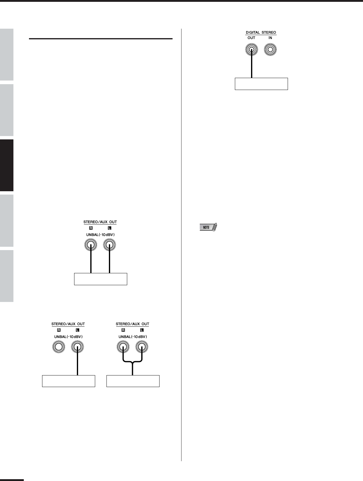
are to be output via the DIGITAL STEREO OUT terminal................................................OUTPUT PATCH (DIGI. ST/AUX OUT PORT) (page 91)
●
Selecting which signals (stereo bus, Rec bus, Aux bus 1/2 or Aux bus 3/4)
are to be output via the STEREO/AUX OUT terminals.....................................................OUTPUT PATCH (DIGI. ST/AUX OUT PORT) (page 91)
●
Directly outputting the input channel signals 1-8 and
9-24 (mLAN) via the output terminals/channels.............OUTPUT PATCH (mLAN OUT CHANNEL)/(DIGI. ST/AUX OUT PORT) (pages 90, 91)
●
Selecting which signal is to be used for Direct Out:
pre-EQ, pre-fader, or post-fader..............................................................................................OUTPUT PATCH (DIRECT OUT POSITION) (page 91)
■Digital In/Out
●
Enabling/disabling cascade connection of the DIGITAL IN to the stereo bus.......................................................D.IN ST-BUS CASCADE (page 93)
●
Setting the attenuation level when connecting the DIGITAL IN to the stereo bus........................................D.IN ST-BUS CASCADE ATT (page 93)
●
Enabling/disabling conversion of the sampling rate of the signal received at DIGITAL IN. .........................SRC (Sampling rate converter) (page 93)
●
Enabling/disabling dithering of the digital audio
(intentionally adding noise to minimize effects of quantization noise)..............................................................................D.OUT DITHER (page 93)
■Program Change and MIDI
●
Enabling/disabling remote control (including Program Change) over the Multi-Part Editor....................... SHIFT+REMOTE FUNCTION (page 87)
●
Setting the MIDI send/receive channels for Program Change.............................................................................................MIDI CHANNEL (page 94)
●
Determining whether Program Change messages are transmitted/received or not.................................................PROGRAM CHANGE (page 94)
●
Setting a specific Program Change number
to be transmitted when a Scene is recalled................................................................................... PROGRAM CHANGE ASSIGN TABLE (page 94)
●
Using incoming Program Change messages to change Scenes. ..................................................PROGRAM CHANGE ASSIGN TABLE (page 94)
■Others
●
Distinguishing among different 01X units when using Studio Manager.................................................................. STUDIO MANAGER ID (page 94)
Using the oscillator signal and changing its waveform...............................................................................................................OSCILLATOR (page 93)
●
Setting the stereo pan position........................................................................................................................................................................PAN (page 99)
●
Adjusting the send level. .............................................................................................................................................................................SEND (page 100)
●
Setting the transmission position (pre/post) of the signal sent to AUX....................................................................... AUX 1 - 4 PREPOST (page 100)
●
Using effects..............................................................................................................................................................................................EFFECT (page 102)
●
Inserting an effect in the channel signal path.........................................................................................................................EFFECT PATCH (page 102)
●
Bypassing the effect.................................................................................................................................................................................BYPASS (page 102)
●
Determining whether or not the input channel signal is sent to the Rec bus and stereo bus........................................RECBUS/ST-BUS (page 99)
■Reference materials
●
Remote Functions................................................................................................................................................................. Remote Function List (page 84)
●
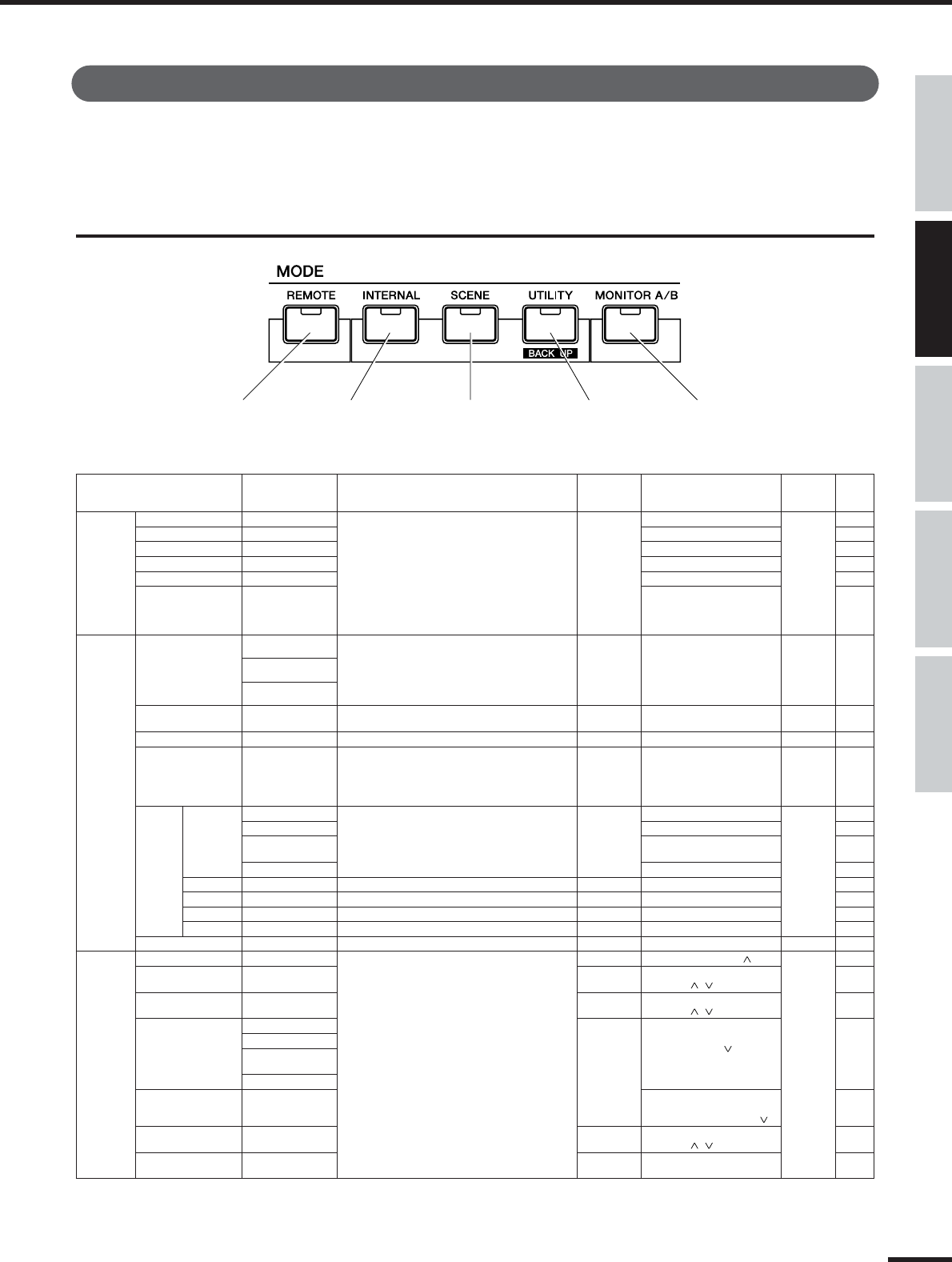
Display indications.....................................................................................................................................Mode selection and Display indications (page 38)
●
Checking the list of available EQ, Dynamics and Effect programs and their parameters....................................................Parameter List (page 115)
●
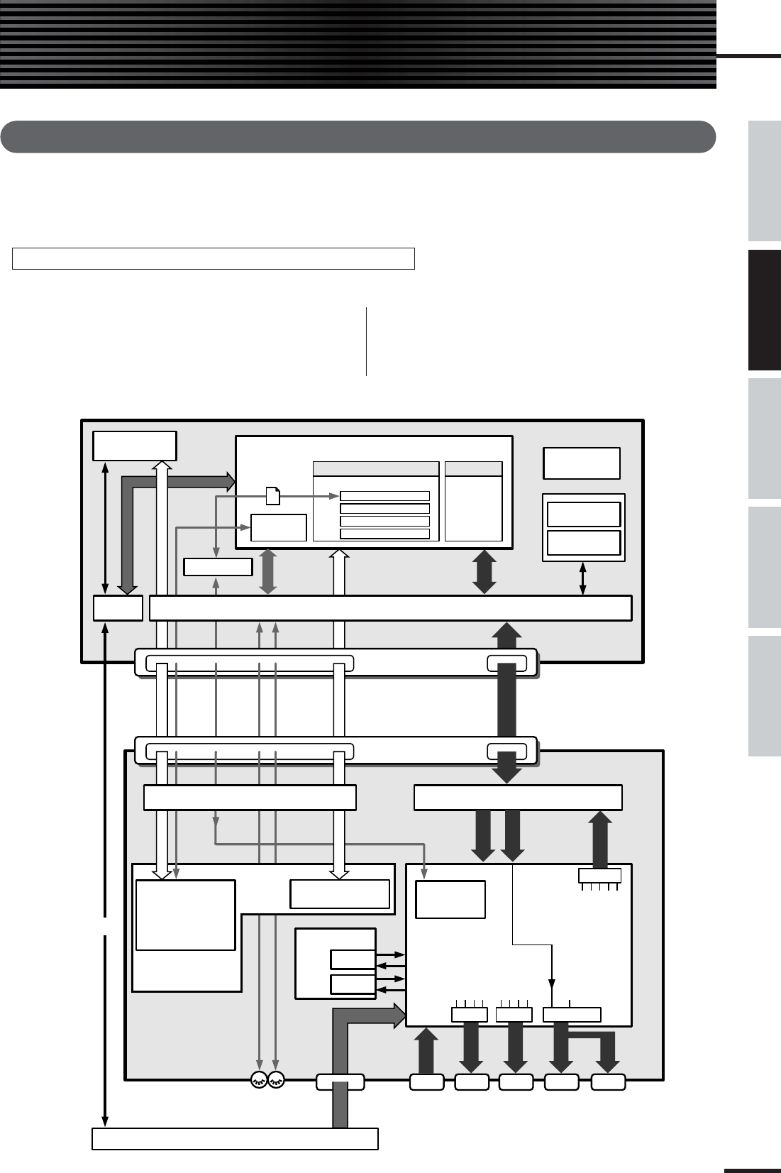
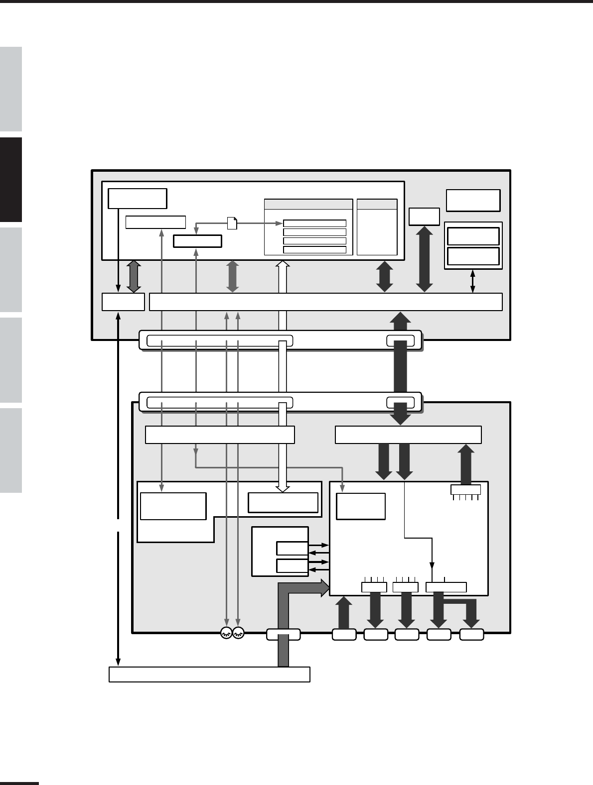
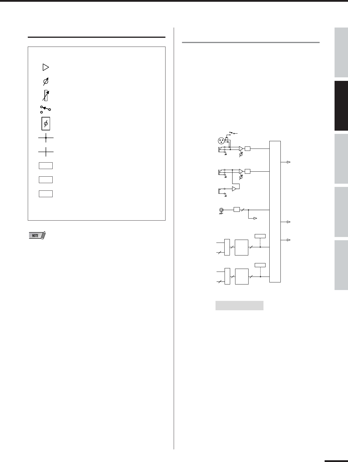
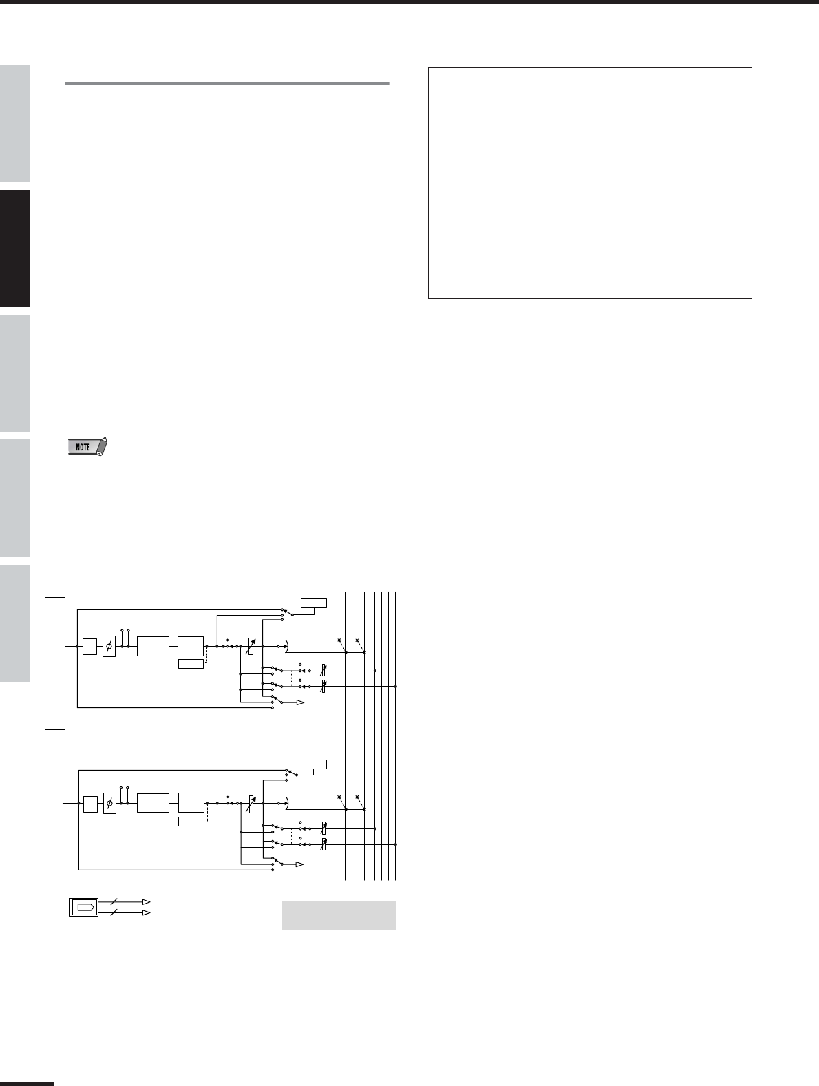
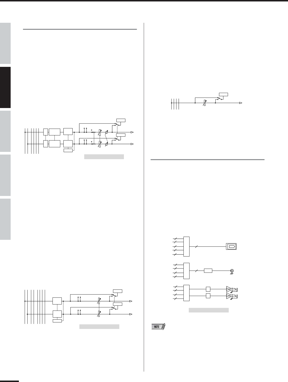
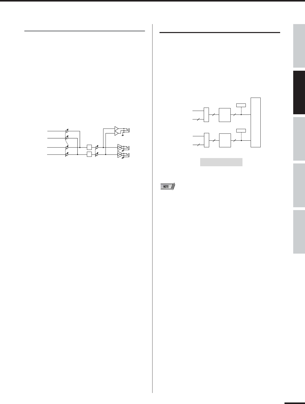
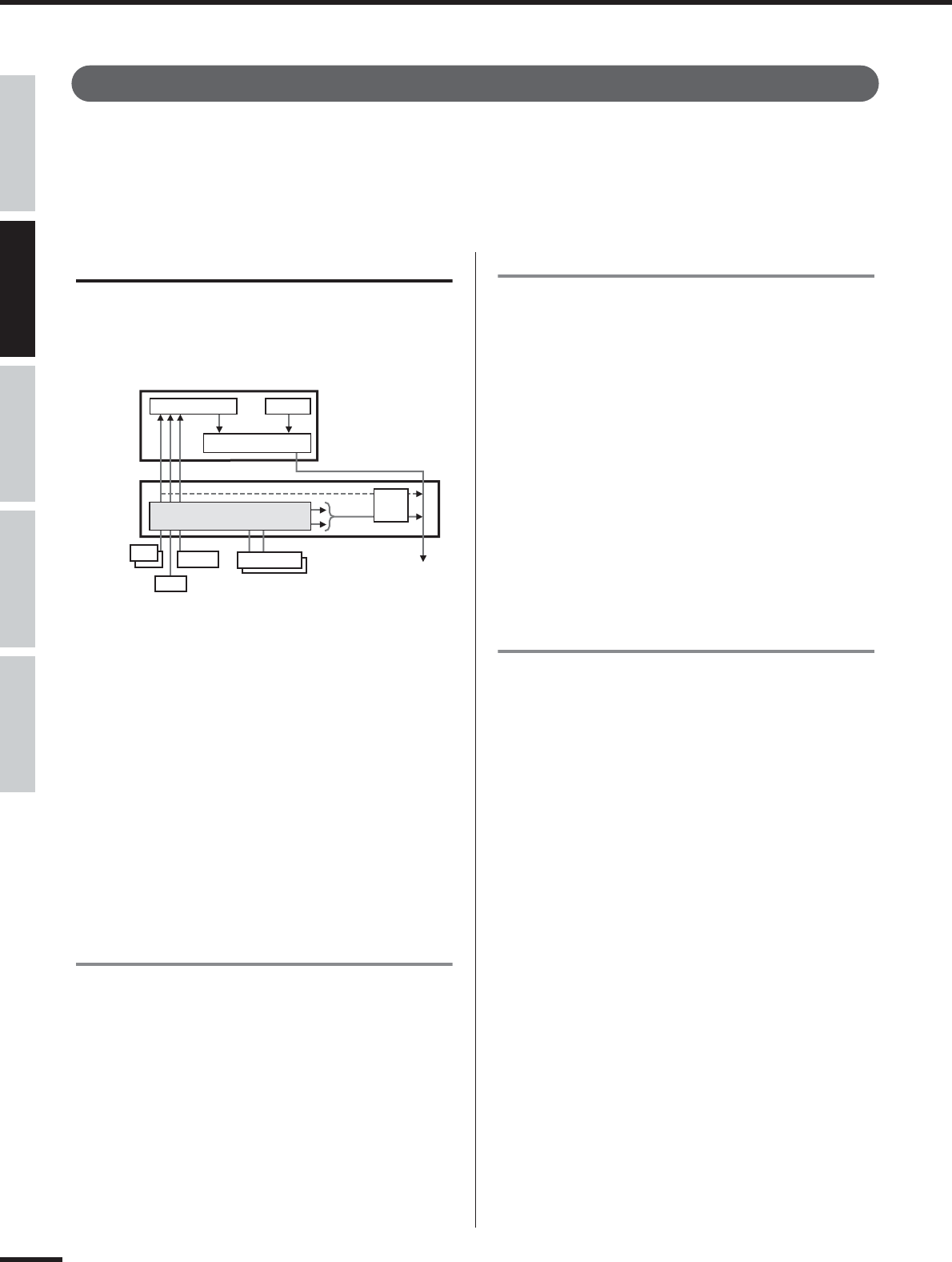
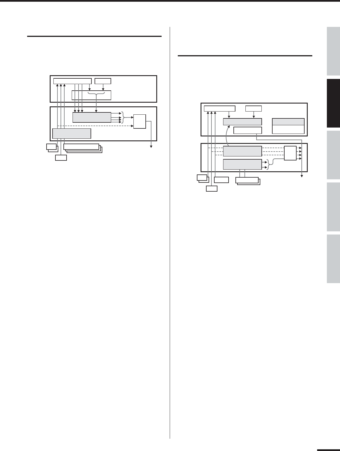
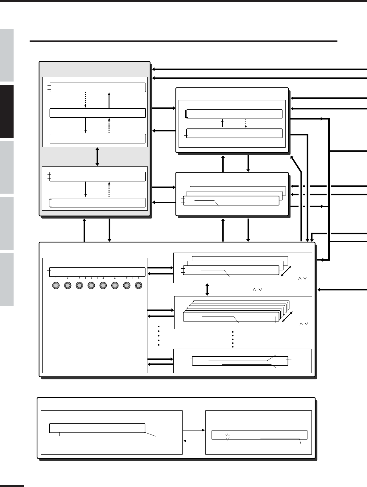
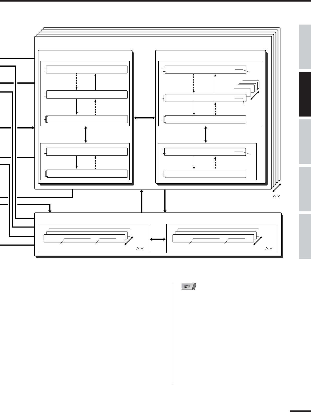
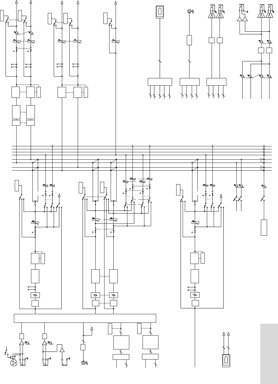
Checking the signal flow of the 01X...................................................................................................................................Block Diagram (End of manual)
●
Understanding the indications in the block diagram............................................................................................................................................(page 28)
●
Using the SQ01 online manual...............................................................................................................................................................(Installation Guide)
●
System requirements for the accessory applications..........................................................................................................................(Installation Guide)
●
Checking the compatible DAW software................................................................................................................................................(Installation Guide)
●
Checking words and terminology used with the 01X..............................................................................................................01X Terminology (page 14)
●
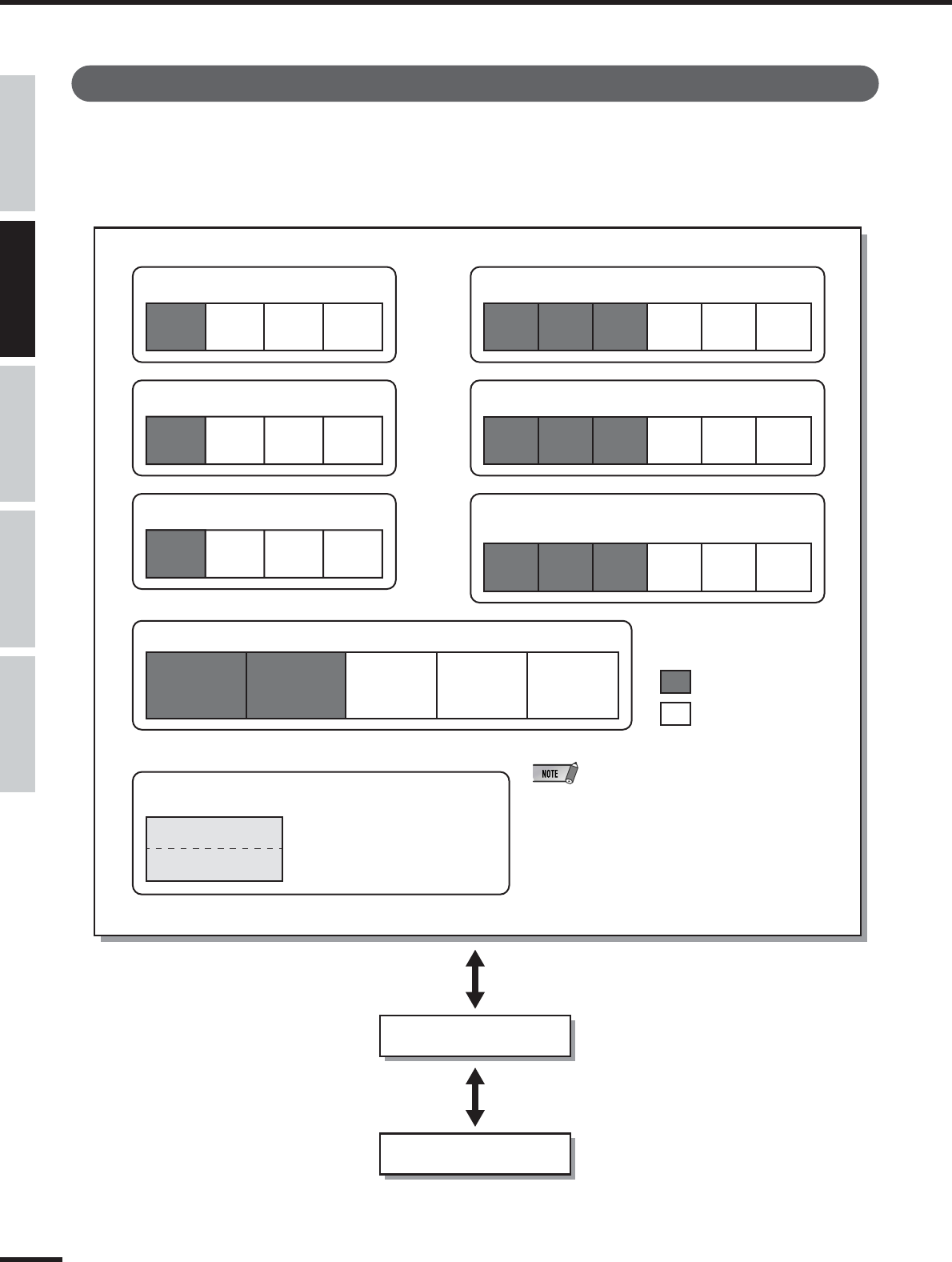
Memory structure of the Libraries...........................................................................................................................................................................(page 36)
●
Checking information on the mLAN MIDI ports.................................................................................................mLAN MIDI INFORMATION (page 95)
■Quick solutions
●
Meaning of the display messages........................................................................................................................................................................(page 143)
Libble nimmt den Missbrauch seiner Dienste sehr ernst. Wir setzen uns dafür ein, derartige Missbrauchsfälle gemäß den Gesetzen Ihres Heimatlandes zu behandeln. Wenn Sie eine Meldung übermitteln, überprüfen wir Ihre Informationen und ergreifen entsprechende Maßnahmen. Wir melden uns nur dann wieder bei Ihnen, wenn wir weitere Einzelheiten wissen müssen oder weitere Informationen für Sie haben.
Art des Missbrauchs:
Forenregeln
Um zu sinnvolle Fragen zu kommen halten Sie sich bitte an folgende Spielregeln:
Lesen Sie zuerst die Anleitung;
Schauen Sie nach, ob die Frage bereits gestellt wurde;
Stellen Sie die Frage so deutlich wie nur einigermaßen möglich;
Erwähnen Sie was Sie bereits versucht haben um das Problem zu lösen;
Ist Ihr Problem von einem Besucher gelöst dann lassen Sie ihn / sie wissen in diesem Forum;
Falls Sie reagieren möchten, so verwenden Sie bitte das Antworten- Formular;
Da ihre Frage für alle Besucher sichtbar ist, sollten Sie lieber keine persönliche Daten erwähnen.
Neu registrieren
Registrieren auf E - Mails für Yamaha 01X wenn:
neue Frage gestellt werden
neue Handbücher vorhanden sind
Sie erhalten eine E-Mail, um sich für eine oder beide Optionen anzumelden.
Das Handbuch wird per E-Mail gesendet. Überprüfen Sie ihre E-Mail.
Wenn Sie innerhalb von 15 Minuten keine E-Mail mit dem Handbuch erhalten haben, kann es sein, dass Sie eine falsche E-Mail-Adresse eingegeben haben oder dass Ihr ISP eine maximale Größe eingestellt hat, um E-Mails zu erhalten, die kleiner als die Größe des Handbuchs sind.
Ihre Frage wurde zu diesem Forum hinzugefügt
Möchten Sie eine E-Mail erhalten, wenn neue Antworten und Fragen veröffentlicht werden? Geben Sie bitte Ihre Email-Adresse ein.