15
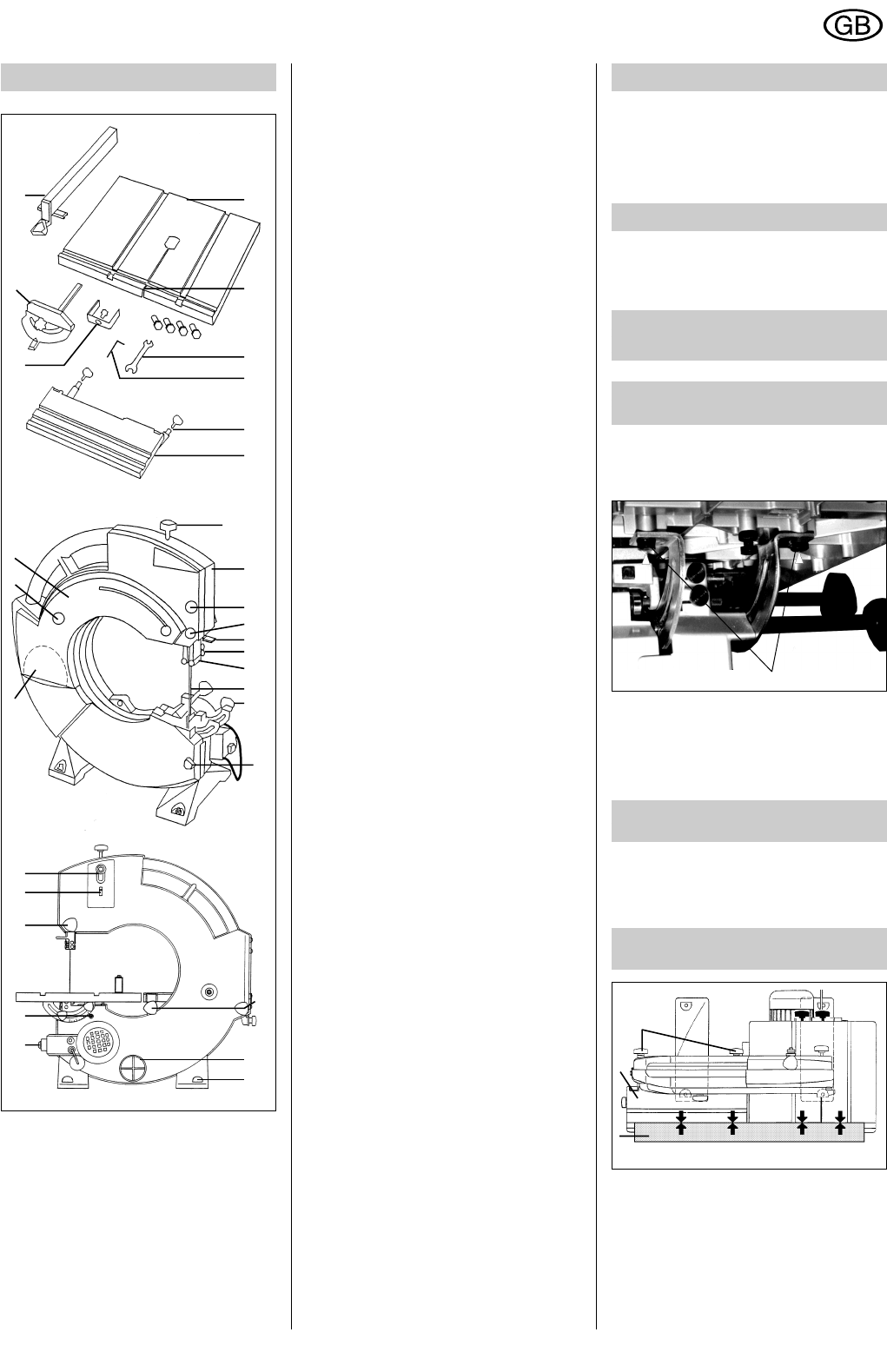
1 Bandsaw table with 4x M8x16 hexagon-
head screws and washers
2 Screw with wing nut, to stabilise the
grooved bandsaw table
3 Double open-ended spanner, 17/13 AF
4 Allen key, size 4 AF
5 Eccentric axis of sanding table (height-
adjustable to bandsaw table)
Sanding table clamp and graduated
scale (-2o, 0o, 45o)
6 Sanding table with 2 knob screws
7 Tightening screw for bandsaw blade
8 3-pulley bandsaw with motor, switch,
mains cable and plug
9 Knob screws for opening the machine
cover
10 Sliding cover lock, unlocks when blade
guard (11) is lowered.
11 Blade guard - always lower to workpiece
height.
12 Upper back guide roller
13 Upper guide pins
14 10 mm bandsaw blade
15 Knob screws for clamping bandsaw
table
17 Knob screws for securing sanding table
18 100 mm dia. chip extraction nozzle
19 Height-adjustable machine feet
20 Switch with undervoltage release.
21 Graduated scale with adjustable stops
22 Knob screws for clamping blade guard
23 Bandsaw-blade tension indicator,
corresponding to blade width
24 Adjuster screw with lock-nut, for adju-
sting the position of the blade on the
pulleys.
25 Self-adhesive Velcro sanding disc - 80
grain sanding sheet
26 Knob screw for clamping sliding cover
27 Sliding cover; for disc sanding, slacken
off the knob screw (26) and push cover
to the right.
28 Bandsawing device (without sanding
belt)
29 Mitre gauge
30 Fence
4 Cecks on unpacking
After unpacking, carefully inspect the
bandsawing machine for any damage which
may have occurred during transportation.
Check that the mains voltage and mains
frequency stated on the rating plate match
the figures for your local mains supply.
5 Functional checks
Before connecting the machine to the mains
supply, check all of the functions of the
bandsawing machine against the Operating
Instructions.
6 Assembly and
adjustment
6.1Mounting the
bandsaw table
1
Fig. 2
As the sanding table can be used as an
extension to the bandsaw table, both tables
should be adjusted at the same time and to
the same settings.
Lay a straight edge (A) along the groove on
both tables. Adjust the bandsaw table
accordingly and tighten the four hexagon-
head screws.
For packing reasons, the bandsaw table is
not mounted on delivery.
Mount the table, securing with the 4x M8x16
hexagon-head screws (1) and washers - do
not tighten fully at this stage.
6.2 Mounting the
sanding table (Fig 3)
Mounting the sanding table (Fig. 3)
Locate the sanding table (6) on the machi-
ne. Secure the table with the two knob
screws (17) at the back of the machine.
6.3 Adjusting the bandsaw
table and sanding table
3 Overview
18
17
8
1
2
3
4
5
6
9
10
11
12
13
14
15
9
7
27
28
29
30
26
25
20
21
22
23
24
19
Fig. 1
Fig. 3
17
6
A
ENGLISH