16
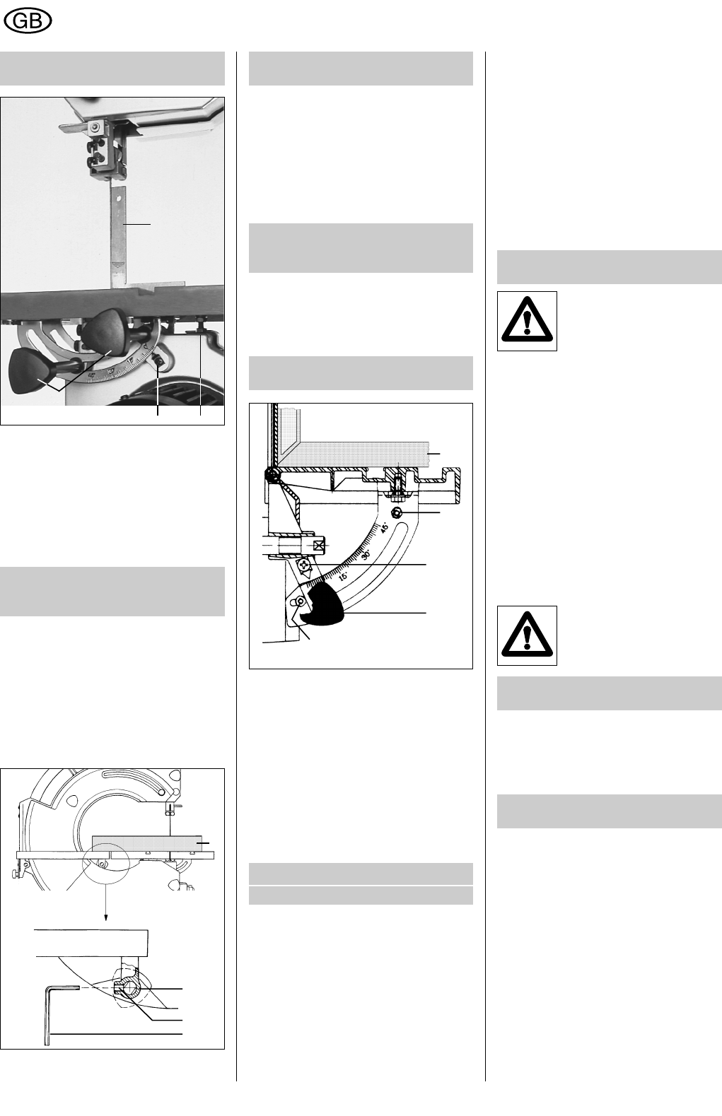
6.4 Adjusting the angle of
the bandsaw table
Place a set square (B) on the bandsaw
table.
The bandsaw blade must not touch the
upper and lower guide pins and back guide
rollers
during measuring.
Loosen the two knob screws (15). Adjust the
bandsaw table to form an exact right angle
with the bandsaw blade.
6.5 Adjusting the
graduated scale of the
bandsaw table (Fig. 4)
Adjustment of the graduated scale of the
bandsaw table (Fig. 4)
Loosen screw (36). Set the pointer to the 0o
mark and tighten the screw.
Loosen the 0° stop (37). Bring it up to the
machine casing and secure with the hexa-
gon-head lock nut.
Swivel the table to 45°. Bring the 45° stop
up to the machine casing and secure with
the hexagon-head lock nut.
6.6 Adjusting the high of
the sanding table
Lay a straight edge (A) over both tables.
Adjust the height of the sanding table to the
height of the bandsaw table.
The height of the table can be adjusted by
turning the two eccentric axes (5). Loosen
the set screws (38) with the size 4AF Allen
key (4). Loosen the knob screws if neces-
sary. Turn eccentric axis (5) with the size
13AF open-ended spanner.
6.7 Setting the distance
between the sanding table
and the sanding disc (Fig. 5)
Setting the distance between the sanding
table and the sanding disc (Fig. 5)
Loosen the set screws (38) on the left and
right table mounting. Set the distance
between table and disc to approx. 2-3 mm.
6.8 Adjusting the graduated
scale of the sanding table
Adjusting the graduated scale of the san-
ding table
Place a set square (B) over the sanding
table. Loosen the securing screw (44). Set
the sanding table to form an exact right
angle with the sanding disc and secure in
position. Slacken off the screw (43), set the
pointer to the 0° mark on the scale and
tighten the screw.
Loosen the 0° stop (45). Move it to the right
and secure in position.
Swivel the table to 45°. Loosen the 45° stop
(42), shift it down and clamp it.
7 Bandsaw blade
7.1 Bandsaw blades
Attention:
Use only sharp and properly set saw
blades.
Only machine-sharpened and correctly set
saw blades give proper cutting results.
Never use damaged saw blades.
The choice of correct bandsaw blade
width depends on the cutting operation
to be undertaken.
For cutting tight curves
with radii from 5 mm, work
only with the fine-cutting
equipment . . . . . . . . . . . . . . . . . 3 mm wide
For cutting curves with
radii from 20 mm . . . . . . . . . . . . 6 mm wide
For longitudinal and cross
cuts, cutting curves with
radii from 40 mm . . . . . . . . . . . 10 mm wide
For straight cutting, and
thick workpieces . . . . . . . . . . . 15 mm wide
7.2 Changing the
bandshaw blade (Fig. 1)
Caution:
Switch off the machine and
disconnect from the mains
supply. Remove the plug!
Unscrew the two knob screws (9) and open
the machine cover.
Slacken off the wing nut (2) on the bandsaw
table and push the screw to the right.
Open the cover (11) of the blade guard.
Turn the screw (7) securing the blade to the
left to slacken off the saw blade.
Remove the bandsaw blade and fit the new
blade around the three pulleys.
Thread the blade between the upper and
lower guide pins (13). Secure the blade with
the screw (7). Close the cover (11) and the
machine cover.
If the cover refuses to close, push the blade
guard down.
Push the screw (2) to the left and tighten
the wing nut to ensure that the grooved
bandsaw table cannot be distorted.
Always wear protective
gloves!
7.2.1 Folding the
bandsaw blade
Hold the bandsaw blade in one hand. Let it
hang down vertically and hold it to the floor
with a foot. Turn your hand through 360°(a
complete circle), as you move it down
towards the floor.
7.2.2 Unfolding the
bandsaw blade
Hold the bandsaw blade away from your
body. Then hold one loop of the blade and
the two other loops will be released. The
bandsaw blade unfolds itself.
Fig. 4
B
3736
15
Fig. 6
43
44
45
42
B
Fig. 5
A
5
38
4
ENGLISH