17
7.3 Adjusting the
bandsaw blade
7.3.1 Correct tension of
bandsaw blade
Turn the tightening screw (7) to the right to
tension the saw blade. The numbers 3, 6,
10, 15 indicate the width of the correspon-
ding saw blades.
Tension the saw blade until the pointer (23)
indicates the relevant number.
7.3.2 Position of the blade on
the pulleys (Fig. 7)
The bandsaw blade must run in the middle
of the pulleys. To adjust, loosen the lock-
nut (24) of the adjusting screw. Rotate the
upper bandsaw pulley by hand in the cutting
direction. Set the adjuster screw (35)
accordingly.
Turn the adjusting screw clockwise ȧȧȨȨ
and the bandsaw blade moves backwards.
Turn the adjusting screw anti-clockwise
ȤȤȥȥ‹ and the bandsaw blade moves
forwards.
The bandsaw blade must not touch either of
the back guide rollers (12). After adjusting,
re-tighten the lock-nut (3) on the adjustment
screw. Adjust the tension of the saw blade if
necessary.
7.4 Adjusting the
bandsaw guide
The blade is supported against lateral
movement and twisting by means of an
upper and a lower guide unit.
Each guide unit consists of two guide pins
(13) and a back guide roller (12).
Always lower the upper guide unit until it lies
as close to the workpiece as possible.
7.4.1 Guide pins
The pins (13) guide the saw blade at the
side. The graphite applied lubricates the
blade and reduces resin build-up.
Adjusting
Clamp the guide head (32) with the knurled
screw (33) so that the guide pins (13) guide
the entire width of the saw blade, but do not
touch the teeth. Clamp the guide pins (13)
with the knurled screws (31). The pins
should lightly touch the saw blade but not
cause it to jam.
Repeat the same procedure with the lower
guide unit.
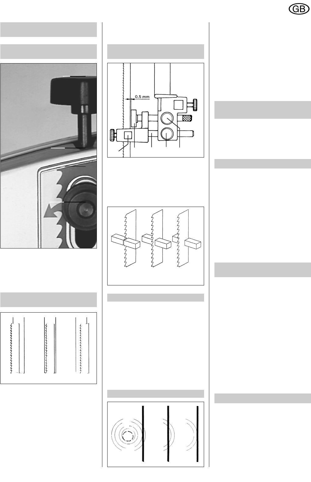
7.4.2 Back guide roller
The roller (12) prevents the saw blade from
being pushed out at the back.
Adjusting
Secure the back guide roller (12) so that the
distance between it and the saw blade is
approx. 0.5 mm. The travel of the back
guide roller is eccentric around its axis.
Turn the eccentric axis to change the
position of the roller (12) relative to the saw
blade.
Repeat the procedure with the lower guide
unit. (34) - securing screw for the back
guide roller.
8 Checks before
switching on
The teeth of the bandsaw blade must be
facing downwards.
Check that the bandsaw blade is correctly
tensioned.
Adjust the guide pins and the guide rollers.
Lower the blade guard to the workpiece.
9 Mains power connection
Connection of the single-phase alternating
current bandsawing machine to the mains
requires a 1.5 mm
2
section 3-core cable and
an extension socket suitable for use with a
shrouded-contact plug.
The rotary current machine is fitted with a
CEE-type shrouded-contact plug. For mains
connection it requires a 1.5 mm
2
section 5-
core cable and a suitable extension socket.
The mains socket to which the machine is to
be connected must be earthed in accordan-
ce with regulations and be protected by at
least a 10 A slow-blow fuse (for 16 A, a
fast-blow fuse is adequate) or an appropria-
te power circuit breaker.
9.1 Direction of bandsaw
blade rotation
The bandsaw blade must rotate so that on
the downward travel side its teeth are
moving from top to bottom. If, in the case of
the rotary current machine, the direction of
rotation is wrong (risk of accident), this can
be remedied by switching over two of the
outer wires in the mains connection cable.
This operation should be carried out by a
qualified electrician only.
Incorrect direction of saw blade rotation can
also be due to incorrect wiring of the mains
socket to which the machine is connected.
Have the socket checked by a qualified
electrician to ensure that the connections
are correct, and have the socket wired
correctly, if necessary.
The machine has been checked to ensure
that the lower bandsaw pulley turns in the
correct direction before it leaves the factory.
10 Vacuum chip extraction
If the bandsawing machine is used over an
extended period for sawing wood or for
commercial use with materials producing
dust which represents a threat to health
(e.g. beech and oak woods), it must be
connected up to a suitable vacuum extrac-
tion device.
Fig. 8
✘✘
Fig. 10
Fig. 11
✘✘
Fig. 7
24
35
23
7
Fig. 9
31
13 12 32 33 34
ENGLISH