S16-IME-6L
12-07
48
S16-IME-6L
12-07
49
Raccordement
Le câble
d’un
T
l’ensemble
teur
coupez
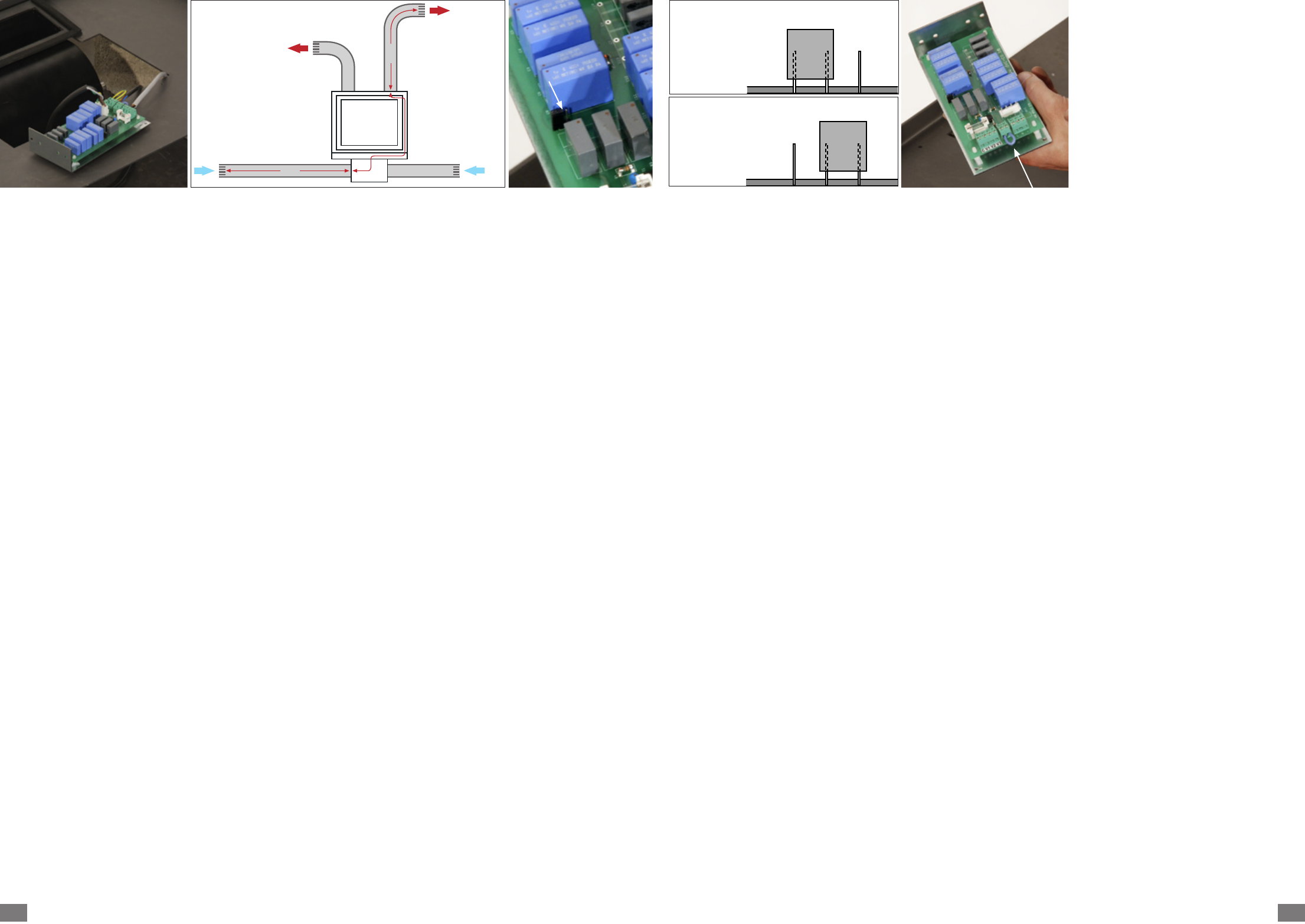
Ajustement
ventilation
Si
ventilation
(A
correct
[photo
(côté
Si,
sont
le
accrue
enlever
aiguilles
* A
plus
B
foyer
s'échappe
C
plus
Raccordement
thermique
L
l’alimentation
la
suffisante. Ainsi,
la
plusieurs
courants
Idem
- Enlever
[photo
- Raccorder l’interrupteur
aux
- L
ultérieurement sur
1
e
3
C17
Aansluiting
De
voorzien
op
geheel
aan
stroom af
Aanpassen
Indien
circuit [schema
(
stelling
[foto 3
(kant
Indien
(
een
drukverliezen
de
wijzers
* A
B
=
ontsnapt
C
Aansluiting
De
van
de
lucht
start
minuten
te
Idem
- V
[foto
- Sluit
zo
- De
de
Collegamento
Il
di
il
prima
[foto
Regolazione
di
Se
ventilazione
condotti
(
fabbrica
[foto
(lato
Se
sono
il
potenza
carico
sui
* A
d'aspirazione
B
dell'inserto
calda
anteriore).
C
convettiva
Collegamento
L
l’alimentazione
se
è
l’accensione,
solo
fastidiose
dicasi
- T
- Collegare
morsetti
- L
sul
Conexión
El
de
Compruebe
conjunto
térmico
después
Ajuste
Si
ventilación
(A
es
3
(lado
Si,
mayores (A
necesitará
la
y
derecha (lado
* A
aspiración
B
del
caliente
C
expulsión
Conexión
El
alimente
del
este
durante
transcurridos
así
Lo
- Elimine
[foto
- Conecte
bornes
- A
térmico
Ligação
O
um
V
antes
[fotografia
corrente
Regulação
Se
ventilação
(A
fábrica
esquema
(lado
Se
da
C
mais
de
direito (lado
* A
maior
B
recuperador
C
aquecimento
Ligação
O
a
temperatura
suficiente.
ventilação
minutos
incómodas.
- Retire a
[fotografia
- Ligue
terminais
- O
ultimamente
Connecting
The
connector
T
thermal
after
Adjusting
If
[diagram
the
[pict.
(J2,
If,
longer
will
the
place
(side
* A :
duct
B
stove
C
Connecting
The
the
temperature is
turning
the
several
cold
- Remove
- Connect
terminals.
- Thermal
stove
A
b
5
2
J 2
A
4